

BTS INSTALLATION GUIDE · DIODE DYNAMICS
Honda Talon A-pillar light installation guide
Install the matched SS3 or SS5 two-pod kit on a supported 2019–2025 Honda Talon. Confirm windshield and aftermarket-cage clearance before starting.
Confirm the kit and prepare your tools
Each kit includes two selected Combo pods, DD7907P Talon mounts, a DD4093 dual-output harness and hardware. Other vehicle lights and the optional rectangular rocker are separate. Check the exact kit and vehicle before removing panels.
Prepare 10 mm, 13 mm and 14 mm tools, a 5 mm Allen key, a trim tool or flat screwdriver, a bubble level and cable ties. Follow the vehicle electrical service procedure. Do not assume compatibility with a windshield or aftermarket cage.
1. Remove the hood and access fasteners
Park safely and follow the vehicle electrical service procedure. Twist both hood clamps clockwise, release the four corners and lift off the hood. Remove six plastic push clips, then the four 10 mm bolts, five 5 mm Allen bolts and two additional clips identified in the original figures. Keep the factory hardware for reassembly.
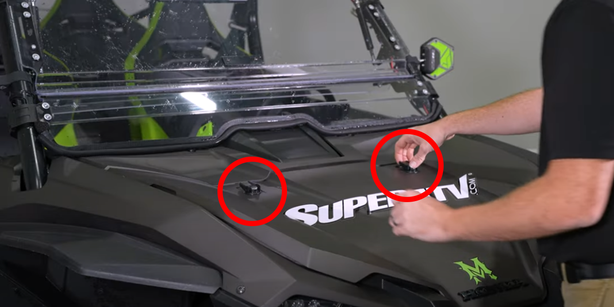
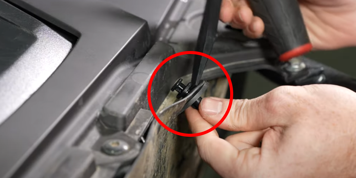
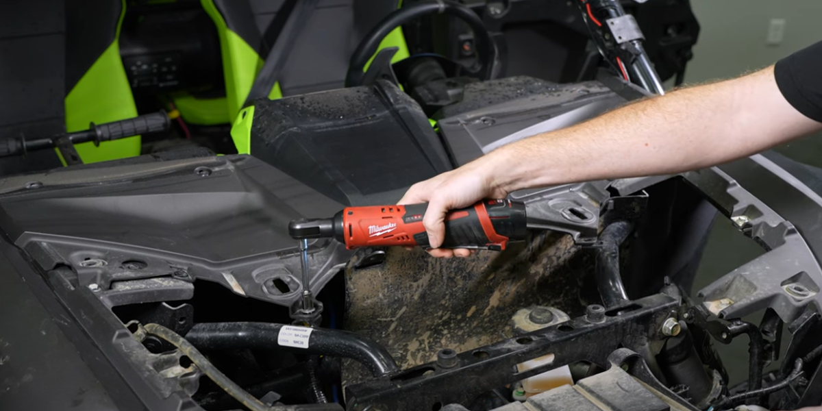
2. Fit and level each vehicle bracket
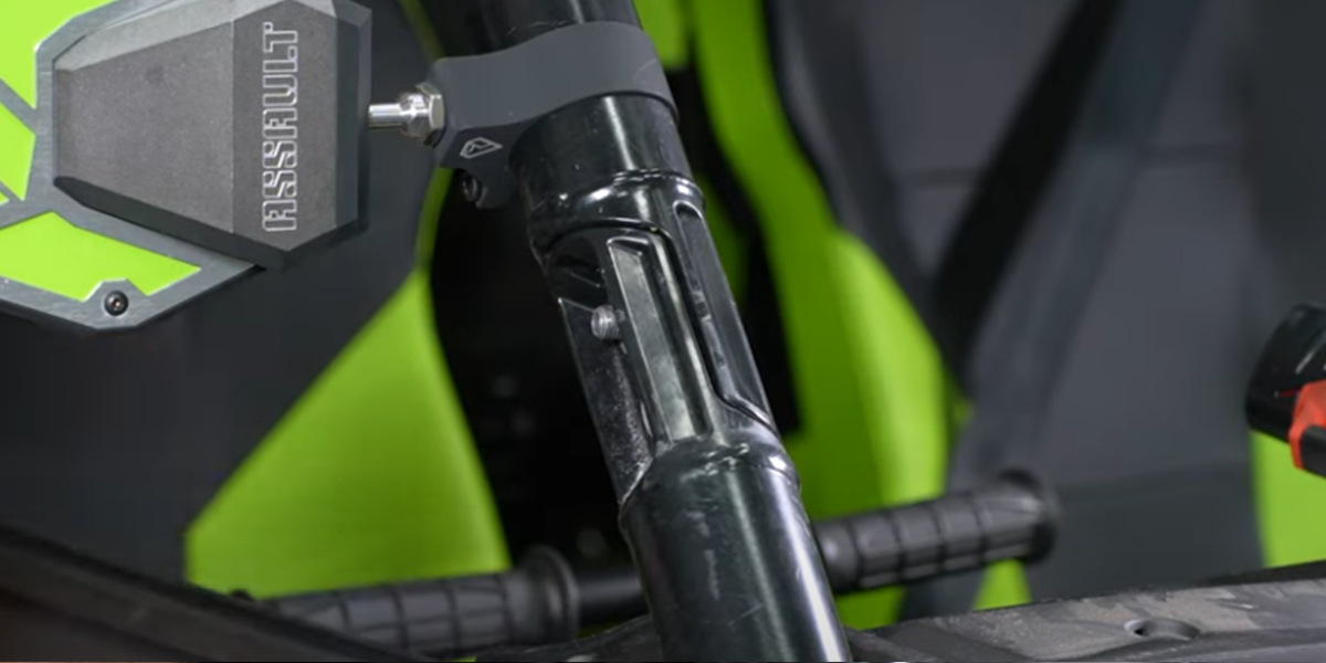
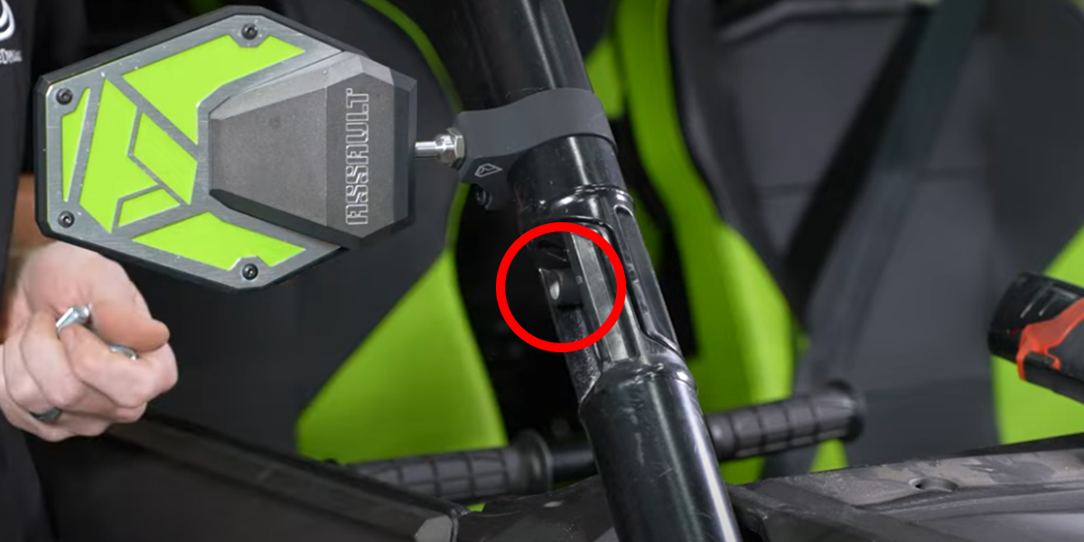
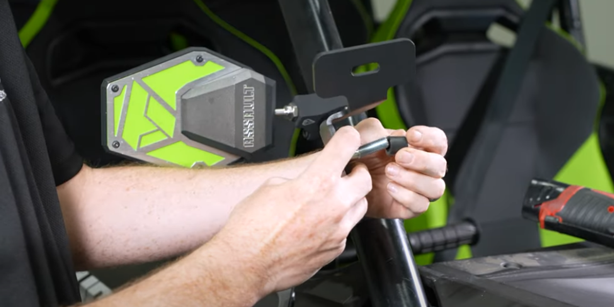
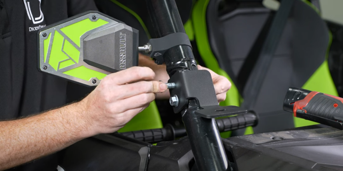
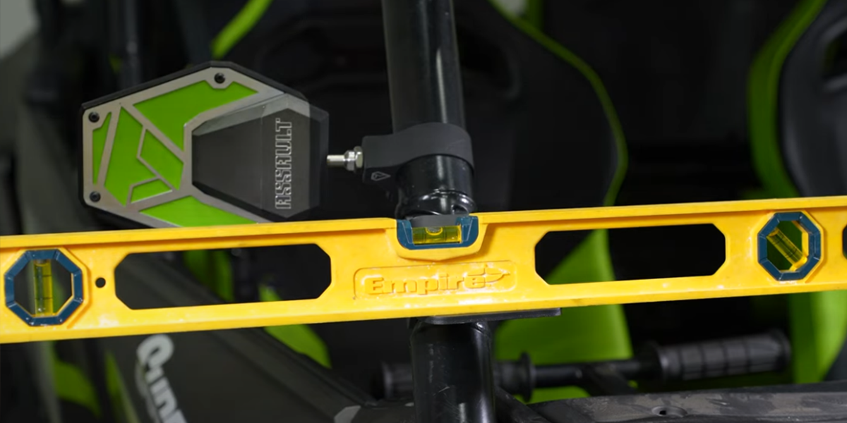
Remove the upper factory bolt with 13 mm and 14 mm tools. Insert that bolt from the inside to temporarily retain the mounting position, then remove the lower bolt. Place the supplied spacer over the retained upper bolt. Fit the A-pillar bracket with the supplied lower bolt and spacer. Use the second supplied bolt to push out the temporary factory upper bolt while retaining its spacer. Secure with the factory nuts, level the bracket and repeat on the opposite side.
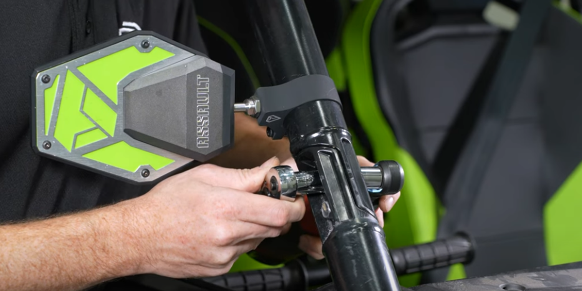
3. Assemble the selected pods
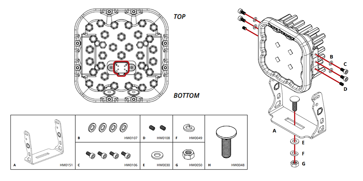
For SS3, position the nylon rings inside the pod mounting ears and slide the universal U-bracket over the back. Fit the supplied aiming screws and washers hand-tight. For SS5, use its own assembly diagram and keep the pod upright as marked. Do not substitute hardware instructions between the two pod families.
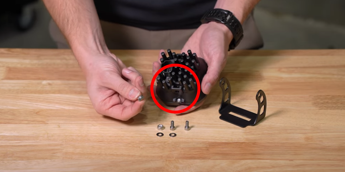
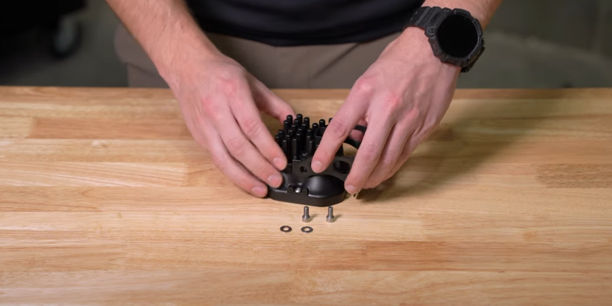
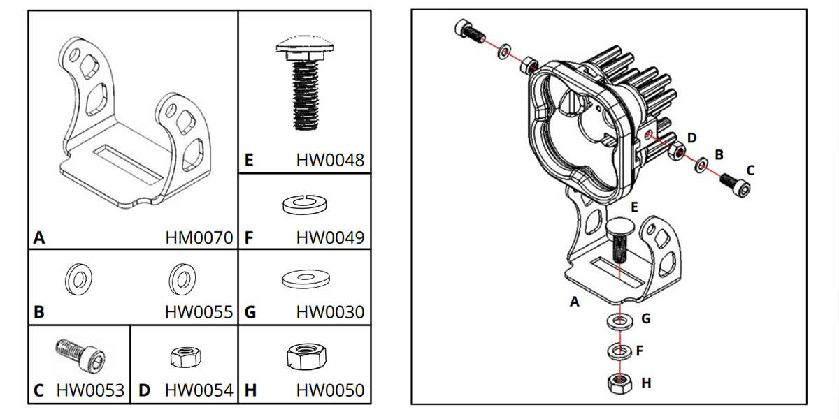
Use the diagram for your pod family
4. Mount the pods to the platforms
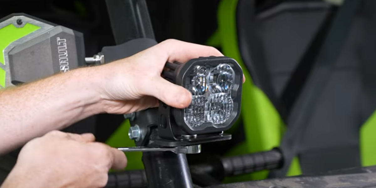
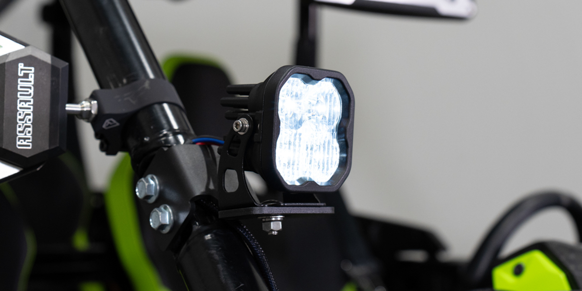
Place each assembled pod on its vehicle platform. Fit the supplied carriage bolt, washer, lock washer and nut, then secure the bracket with a 13 mm wrench. Leave the aiming adjustment accessible until the final test. No tightening torque is specified in the vehicle guide.
5. Connect and route the harness
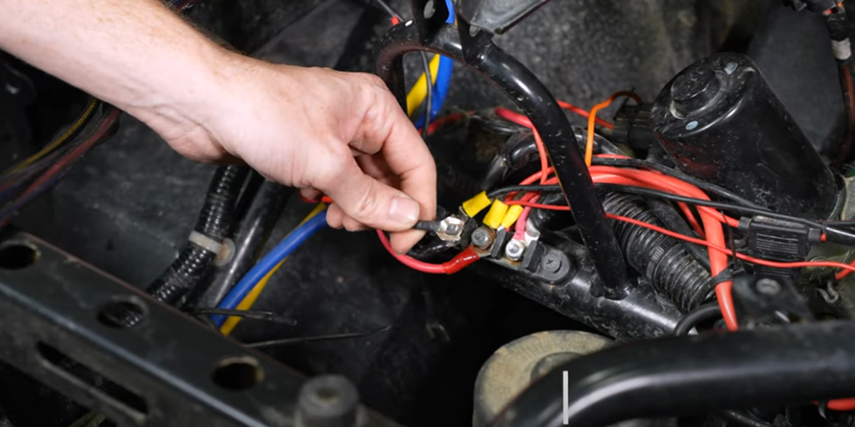
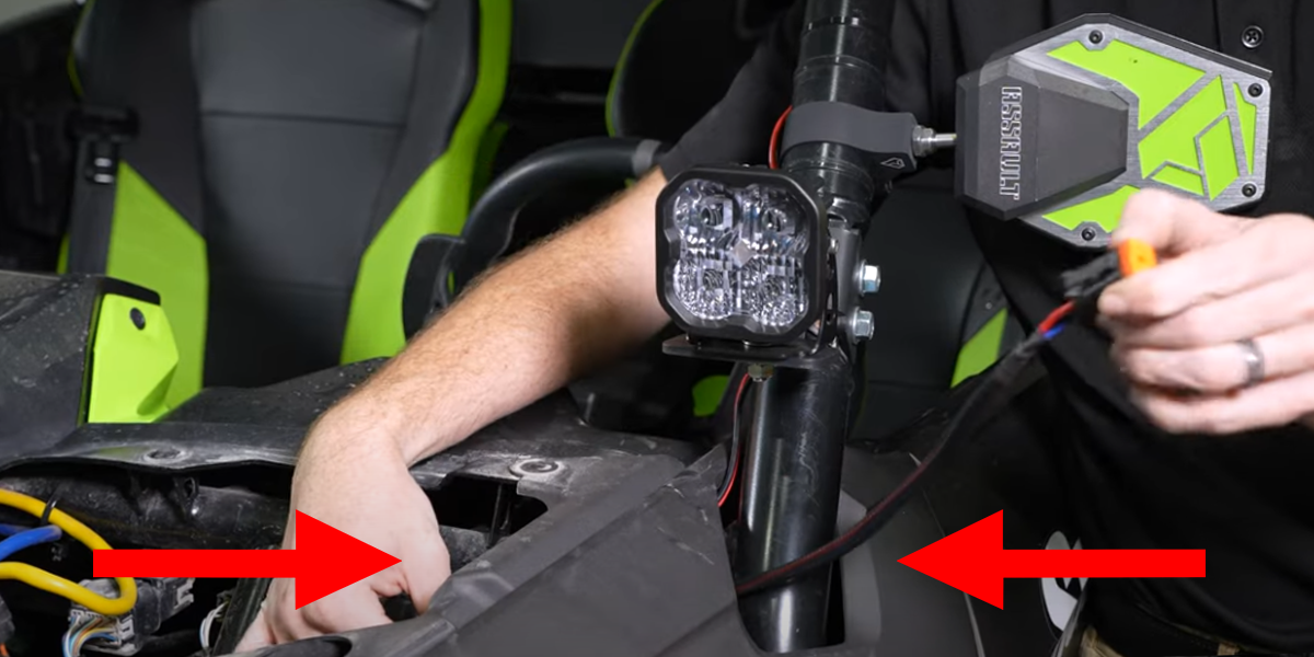
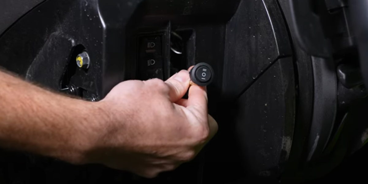
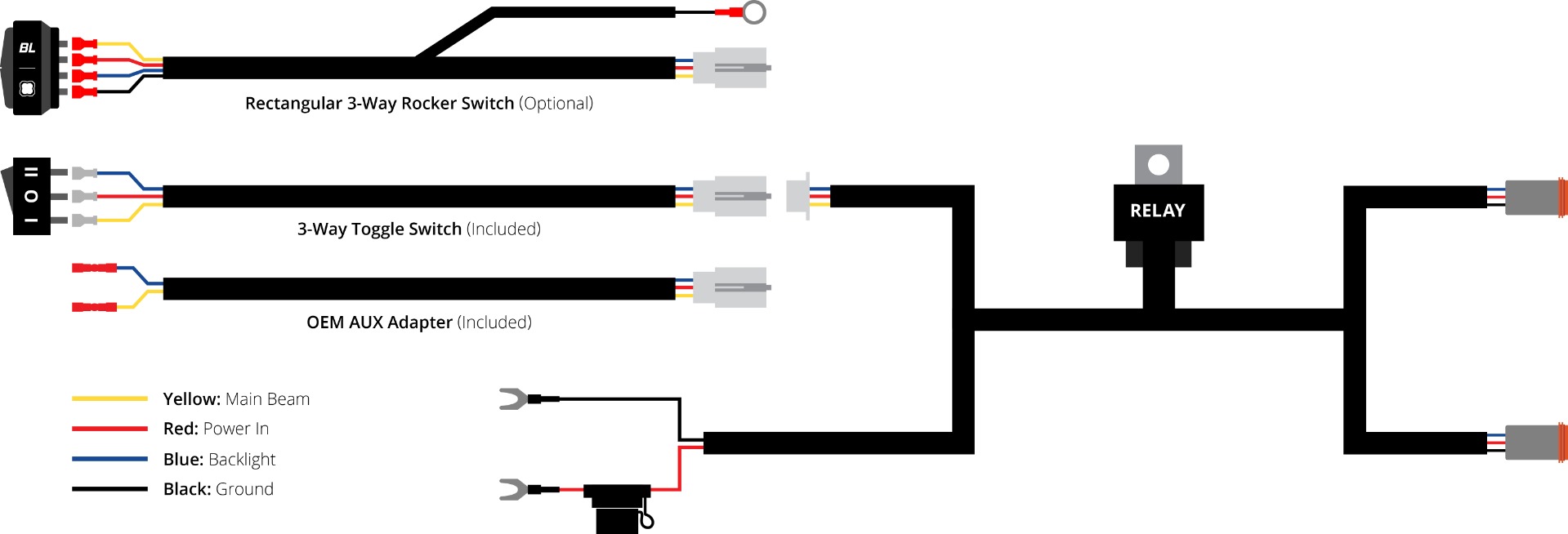
With electrical power isolated according to the vehicle service procedure, identify the positive and negative bus-bar terminals. Use a 10 mm wrench to fit the corresponding harness leads. The manufacturer illustrates a slight bend to the fork terminal for clearance; preserve its secure seating and insulation. Route the DT leads beneath the cowls toward the pods, clear of hot and moving parts. Position the included toggle at a suitable location and secure its lead with cable ties.
Optional rectangular rocker switch
The rocker is sold separately. Disconnect the included toggle at its white inline connector and connect the compatible rectangular rocker. Route it to a suitable switch blank and seat it fully after checking clearance. Attach the black ring-terminal lead to a suitable chassis ground for switch illumination. This diagram describes the switch harness, not the pod pinout.
6. Test, aim and restore the panels
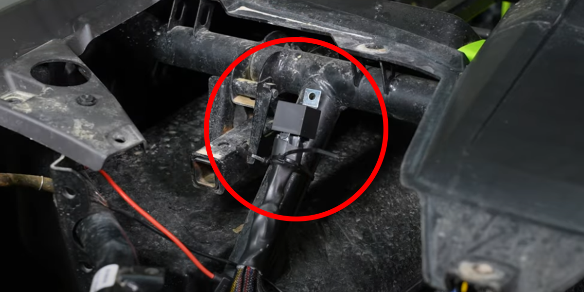
Restore power according to the vehicle service procedure. The ignition must be on when using this specified bus-bar connection. Test the main beams and backlights, aim both pods and secure their adjustment hardware. Tie up the relay and excess wiring, then reinstall the hood and retained fasteners. Check that panels, cables and mounts remain secure.
Program the White SS5 backlight
The White SS5 kit supports White, Red, Blue, Green, Purple, Yellow, Amber and Teal backlight colours. Yellow SS5 and both SS3 main-beam colours have fixed Amber backlighting. This does not change main-beam colour.
- Start with backlight power off.
- Cycle power on and off three times within three seconds, spacing each on action about one second apart.
- Continue at that pace to select the colour.
- Leave the desired colour on for five seconds to save it, then switch it off.
Resynchronize White SS5 pods
Enter programming mode with the same three cycles. Continue through every colour twice, at least sixteen total cycles. All connected pods reset to White. Leave them on for five seconds to save, then choose another colour if required. Yellow SS5 remains Amber-only.
Original references and video
Original generic SS3 assembly PDF: use its mounting illustration, not its older electrical figures as complete-kit specifications. Original SS5 pod assembly instructions.
Original manufacturer Talon installation instructions. The original guide title ends in 2024; current product fitment includes 2025. Follow the supplied kit and vehicle-specific instructions.
Other lights and accessories shown in the video are separate products.