

BTS INSTALLATION GUIDE
Toyota Tundra SS20 TRD Pro grille installation guide
Install the Standard SS20 kit behind an OEM TRD Pro grille on a supported 2022–2026 Toyota Tundra, with the manufacturer’s original mounting and wiring photographs.
Check the vehicle and supplied kit
An OEM TRD Pro grille is required and is not included. Aftermarket grille fitment is not established. Use the supplied harness and new switch; the factory TRD Pro light switch is incompatible. The original shared article also mentions Classic SS18: this guide follows the current SS20 mounting branch and does not substitute SS18 wiring, power or controls.
Tools: Ratchet; 10 mm and 12 mm sockets; T6 Torx driver; Phillips screwdriver; suitable trim tools.
Park securely, switch the vehicle off and follow its service instructions for electrical isolation and safety-related fasteners. Use a qualified installer if you are not equipped for the work. Compare the supplied connectors and hardware with the exact instructions before proceeding. Original photographs and annotations remain intact; open any figure at full size.
1. Release the upper bumper
Open the hood. Remove the four upper bumper bolts with a 10 mm socket and the two push clips with a trim tool. Disconnect the four harness connectors beside the clips.
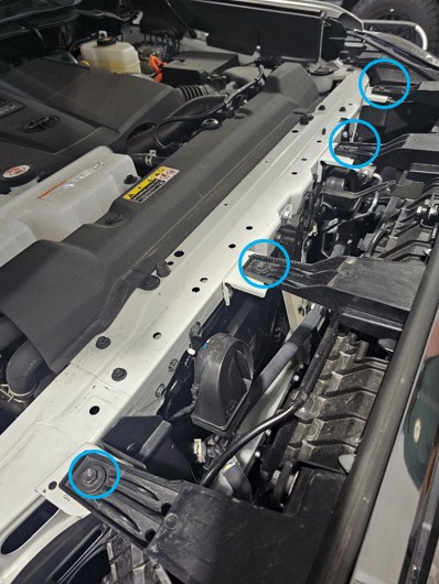
2. Release the lower bumper
Remove the four lower bumper bolts with the 10 mm socket. Keep removed hardware organised for reassembly.
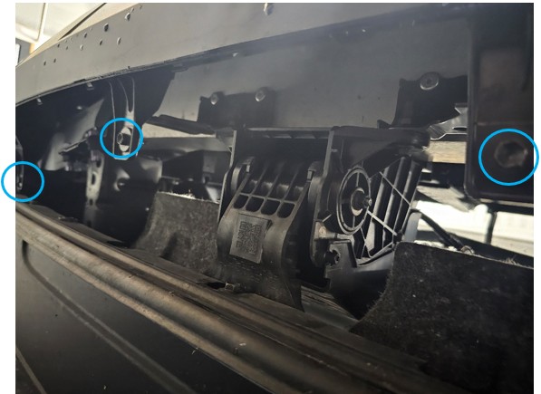
3. Open both wheel-well areas
Remove the five 10 mm fasteners in each wheel well. Move the liners aside enough to reach the bumper clips.
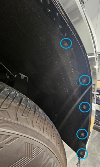
4. Release the fender flares
Reach behind each flare and release its two bumper clips. Ease the flare away without forcing it; repeat on the other side.
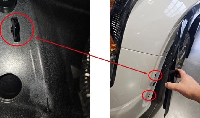
5. Remove and support the bumper
Release the bumper from each wheel-well edge toward the centre. Lift it away carefully and place it face down on a protected, padded surface.
6. Remove the active grille shutter
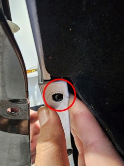
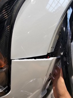
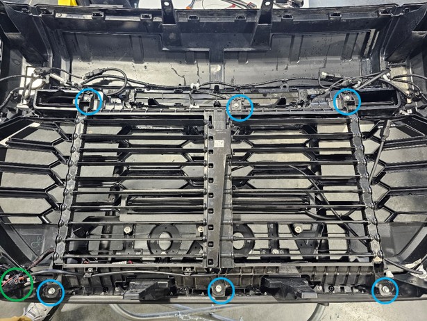
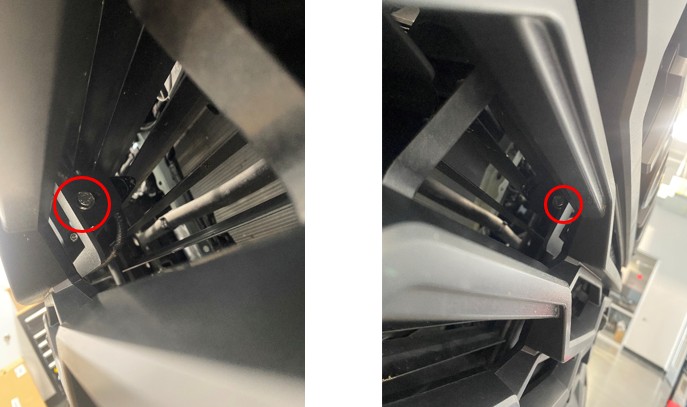
Disconnect the shutter harness and remove the six 10 mm fasteners shown. Put the shutter assembly aside safely.
7. Remove the radar assembly
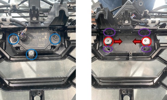
Remove the two bolts and Phillips screw at the radar sensor. Retain the slide nuts and release the sensor-cover clips for later reinstallation.
8. Remove the camera bracket
Remove the two Phillips screws holding the camera bracket. Record the camera orientation before moving it.
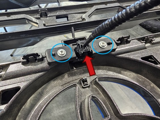
9. Separate the camera from its mount
Disconnect the camera harness. Remove its two T6 Torx screws and retain them with the camera.
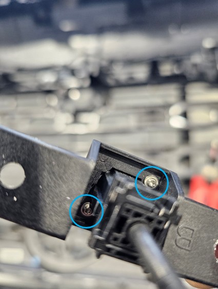
10. Release the upper grille surround
Remove the four Phillips screws and release the upper surround clips. Support the panel as the last clips release.
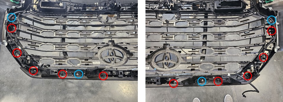
11. Release the left surround
Remove the two Phillips screws and release the clips on the left grille surround.
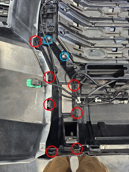
12. Release the right surround
Repeat the two-screw and clip removal on the right grille surround.
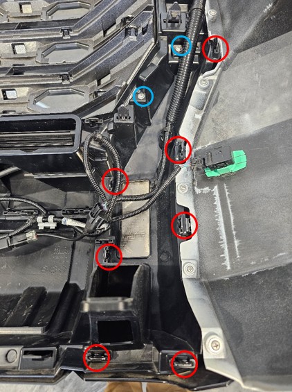
13. Release the lower surround
Release the retaining clips along the lower grille surround and lift it away.
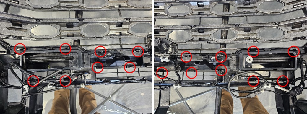
14. Remove the original grille
Remove the four Phillips screws and the remaining clips securing the grille.
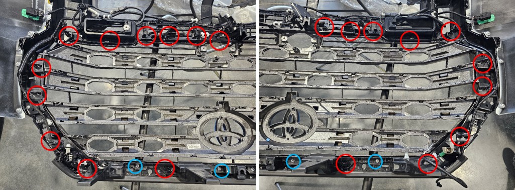
15. Fit the OEM TRD Pro grille
Position the OEM TRD Pro grille, seat its clips and reinstall the screws. The grille is required but is not supplied with this light-bar kit.
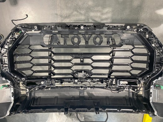
16. Refit the radar assembly
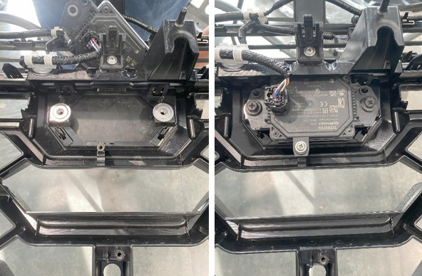
Reinstall the radar sensor and cover using the retained factory hardware and slide nuts. Preserve its original orientation.
17. Refit the surrounds
Refit the lower, left, right and upper surrounds, in that order. Check clip engagement before moving on.
18. Relocate the camera
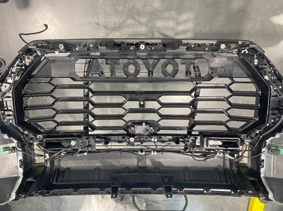
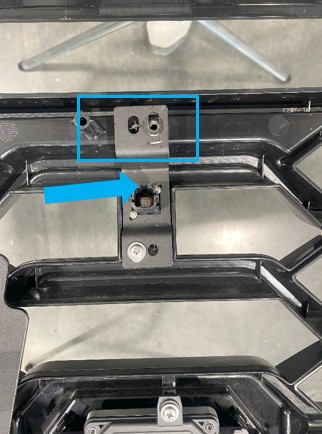
Attach the camera to the supplied relocation mount with the original T6 screws. Follow the illustrated locking-tab orientation when seating the mount in the grille.
19. Mount the SS20 in its bracket
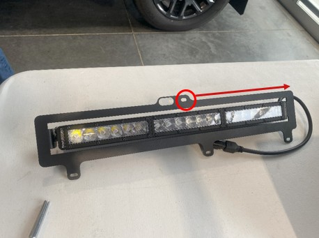
Use the supplied hardware to fit the SS20 in the grille bracket, with its harness toward the keyhole end. Slide the bar fully forward and leave the hardware loose enough for final aiming. The manufacturer states that this mounting procedure is shared with the earlier SS18; the original photograph illustrates bracket position, not the SS20 lamp specification.
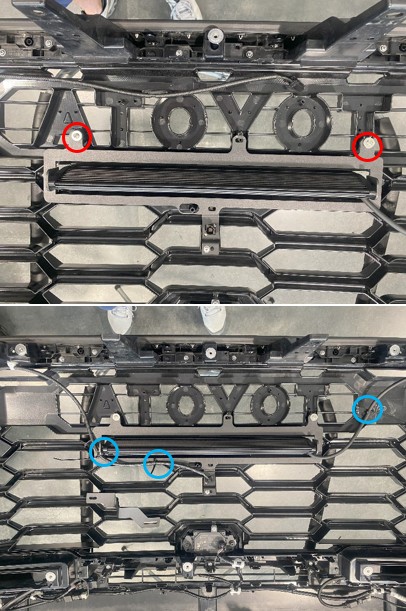
20. Attach the grille bracket
Secure the bracket to the TRD Pro grille with the supplied screws and washers. Do not overtighten the grille fasteners.
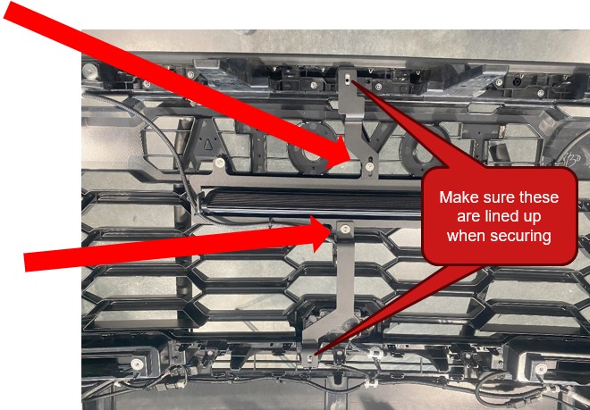
21. Fit both support brackets
Fit the upper and lower support brackets with the supplied hardware. Align the locations marked in the original figure before tightening.
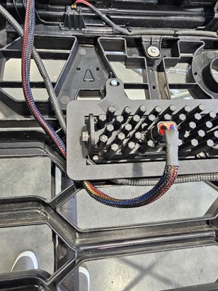
22. Route the bar connector
Run the bar harness along the grille and secure it with the supplied ties, leaving the connectors and nearby hardware clear.
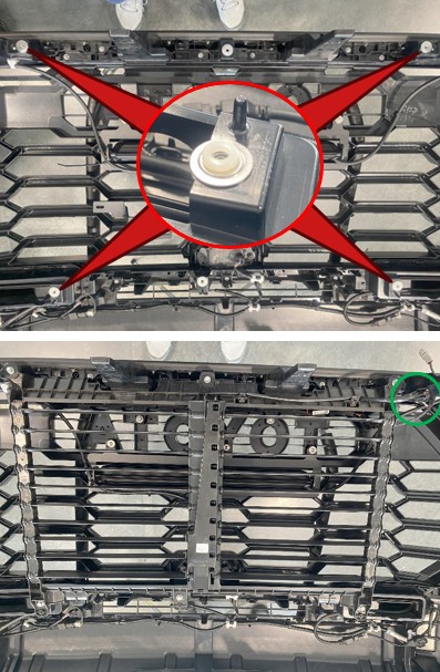
23. Refit the shutter with its spacers
Use the supplied spacers when reinstalling the active grille shutter. Reconnect its harness and preserve the bar’s fully forward position.
24. Refit the bumper
Return the bumper to the vehicle and reverse the removal sequence. Reconnect the disconnected vehicle harnesses and check that the surrounding panels are seated.
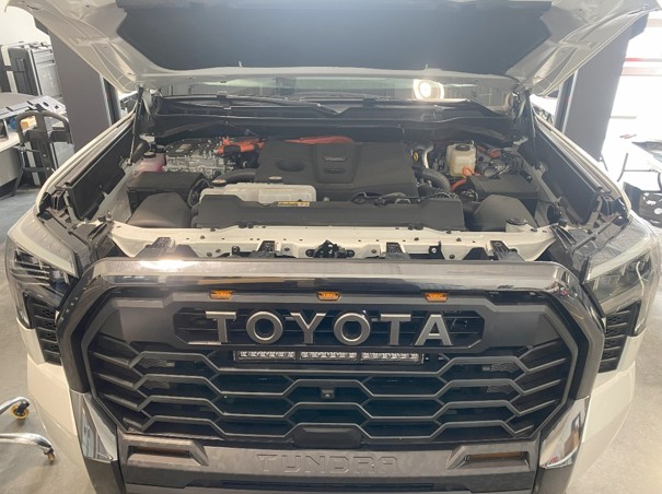
25. Wire the correct power branch
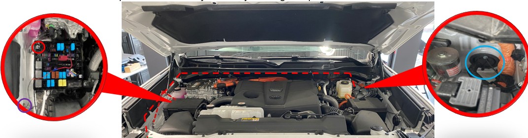
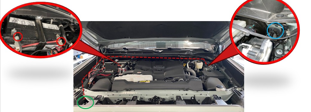
Use the included harness and its new switch; the factory TRD Pro light switch does not control this bar. On a hybrid, remove the fuse cover and use the illustrated positive post (12 mm nut) and ground point (10 mm bolt). On a non-hybrid, the manufacturer uses the battery positive and negative terminals with 12 mm hardware. Follow the vehicle manufacturer’s battery-isolation precautions before electrical work. Route the light-bar output to the front passenger side and the switch lead to the driver-side grommet beside the brake booster. Secure the loom clear of heat, sharp edges and moving parts. The two original figures show the hybrid and non-hybrid branches respectively.
26. Test, aim and finish
After safely restoring power, test the bar and set its aim. Tighten the mounting hardware with the 10 mm socket. Confirm that the fully forward bar and the installed spacers allow the active grille shutter to move without interference.
Tundra TRD Pro grille installation
This original installation video can show the older SS18 bar. Use the current SS20 written steps above, the supplied harness and a new switch.
Original instructions and matching kit
This BTS guide uses original explanatory wording with all relevant original technical figures from the manufacturer’s current HTML article. The article does not provide a downloadable PDF.