

BTS INSTALLATION GUIDE
Can-Am Maverick X3 SS10 shock-mount installation guide
Install the single SS10 shock-mount kit on a supported 2017–2025 Can-Am Maverick X3 using the original manufacturer photographs and exact mounting points.
Check the vehicle and supplied kit
Aftermarket shock mounts can change bracket clearance; confirm the mounting area before starting. This guide is for one Standard SS10 bar and the matched supplied harness. White bars provide eight backlight colours; Yellow bars provide Amber only. Do not substitute SS6 specifications or another harness pinout.
Tools: 10 mm and 13 mm wrenches; 10 mm, 13 mm and 18 mm sockets; ratchet; wire-running tool and tape. The manufacturer estimates 90–120 minutes, depending on the vehicle and installer.
Park securely, switch the vehicle off and follow its service instructions for electrical isolation and safety-related fasteners. Use a qualified installer if you are not equipped for the work. Compare the supplied connectors and hardware with the exact instructions before proceeding. Original photographs and annotations remain intact; open any figure at full size.
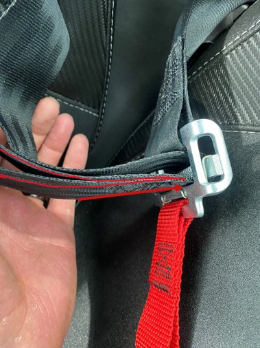
1. Release the passenger belt
Pass the looped end out of the passenger seat-belt attachment as shown to free the seat for removal.
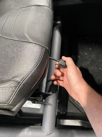
2. Move the passenger seat forward
Use the seat adjustment lever to move the seat fully forward and expose the rear mounting points.
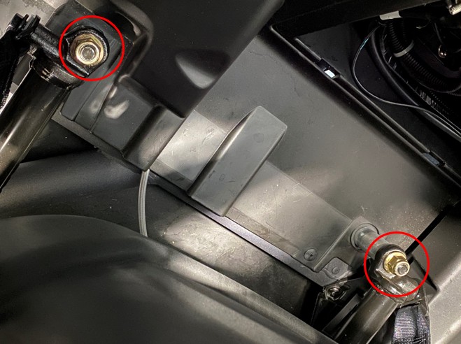
3. Remove the rear seat nuts
Use an 18 mm socket to remove the two rear gold locking nuts shown in the photograph.
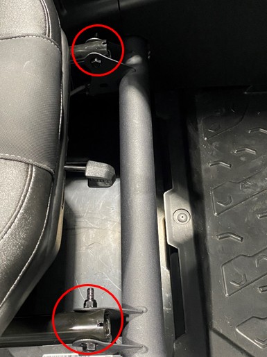
4. Remove the front seat fasteners
Move the seat fully back. Use a 13 mm wrench and socket to remove the two front bolts and locking nuts, then lift the seat out carefully.
5. Isolate the battery safely
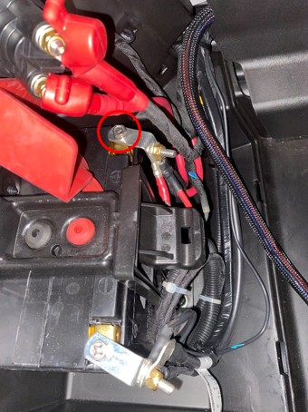
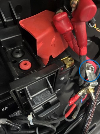
Before connecting the relay or working at the busbar, isolate the battery following the Can-Am service procedure for your exact vehicle. The original article photographs identify the red positive lead and 10 mm hardware; they are retained as location references, not a substitute for the vehicle maker’s safe disconnection order. Secure disconnected leads against accidental contact.
6. Release the rear console panel
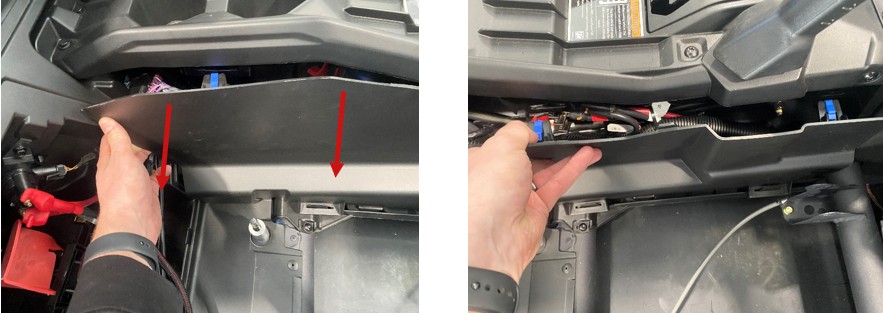
Starting at the top-left corner of the rear passenger-side console panel, release the clips and work forward. Retain the panel for reassembly.
7. Release the front console panel
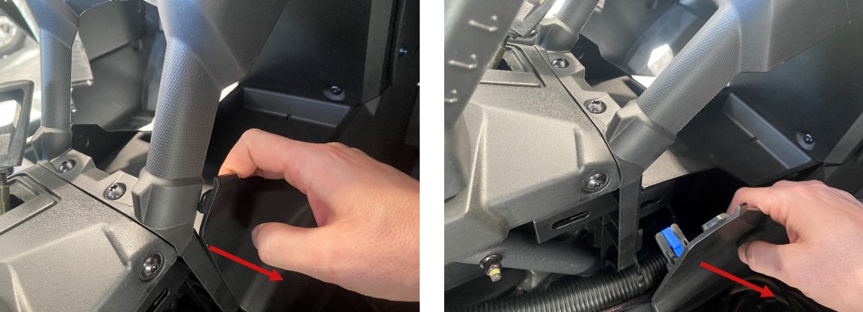
Remove the forward passenger-side console panel using the same careful clip-release method.
8. Expose the busbar
Lift back the rubber protector and loosen the top two 10 mm bolts at the illustrated busbar mounting area.
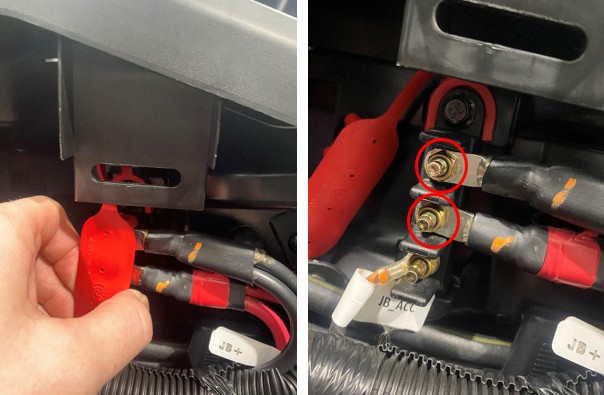
9. Position the harness relay
Mount the supplied harness relay at the busbar location shown. Prepare the power and ground leads while the supply remains isolated.
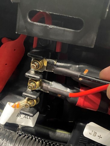
10. Connect and route the harness
Place the black lead at the negative connection and the red lead at the positive connection, then secure the 10 mm hardware. Replace the protector and tuck the relay where the panels can refit. Route the connector and switch leads through the console to the driver-side footwell, clear of hot and moving parts.
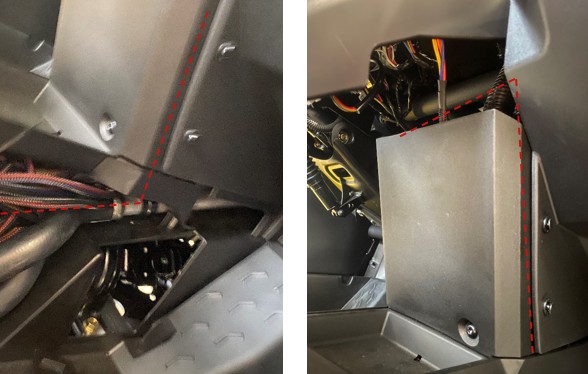
11. Position the switch
Choose a suitable switch location and route the leads to it. Follow the supplied harness’s wiring diagram and connector labels. The original photograph shows the source harness arrangement; do not assume wire colours or terminal positions for a different revision. Leave the switch loose until operation is checked.
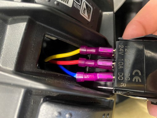
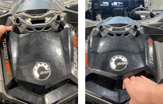
12. Remove the hood panel
Release the hood panel from its five attachment points, beginning at the top-left position shown. Put it aside safely.
13. Pass the connector through the firewall
Use a wire-running tool from the driver-side footwell through the illustrated firewall route. Secure the Deutsch connector to the tool and draw it forward without straining the loom.
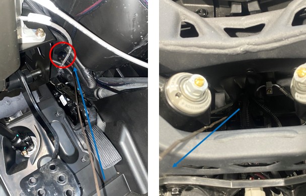
14. Use the centre access opening
Route the connector through the centre opening shown, keeping the loom clear of the nearby suspension hardware.
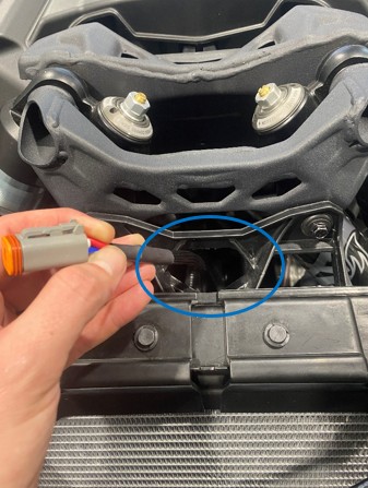
15. Remove only the illustrated bracket fasteners
Use a 10 mm wrench and socket to remove the two factory fasteners marked in the figure. These are the identified light-bracket mounting points; do not loosen the large shock-pivot bolts. Retain the removed hardware.
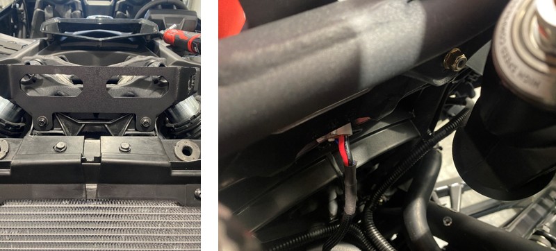
16. Install the vehicle bracket
Fit the supplied light-bar bracket with the retained bolts and washers. Start the nuts by hand, then secure them using the 10 mm tools.
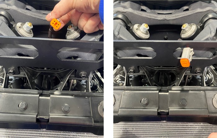
17. Bring the harness to the bracket
Guide the harness through the gap on the right side of the bracket area shown in the preceding figure. Avoid trapping the loom behind the bracket.
18. Connect the SS10
Plug the Deutsch connector into the bar and check that its locking tab engages fully.
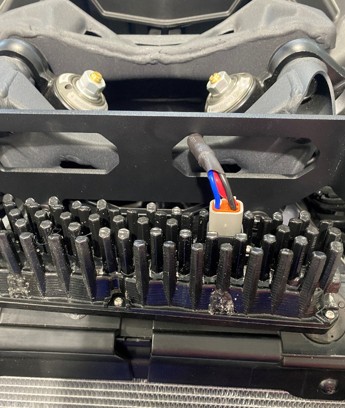
19. Mount, test and aim
Fit the SS10 with its connector toward the driver side. Use the middle mounting holes and supplied bolts, leaving enough movement for aiming. Restore battery connections using the vehicle service procedure, test the switch and set the aim before securing the mounting hardware.
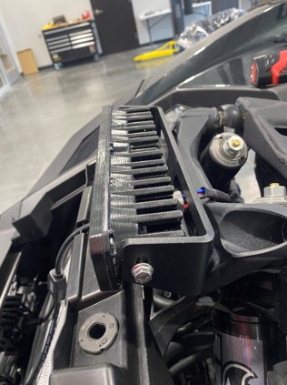
20. Secure and reassemble
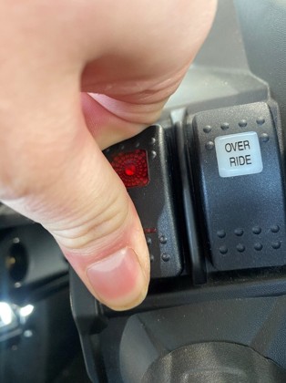
Seat the tested switch, secure excess loom inside the console and refit the console panels. Reinstall the passenger seat and belt attachment by reversing removal and following the vehicle maker’s fastener requirements. Check that wiring cannot interfere with the seat or suspension.
Understanding lumens, lux and candela
This is a manufacturer explanation of lighting measurements, not an SS10 installation video. The current exact installation article provides the illustrated procedure above.
Original instructions and matching kit
This BTS guide uses original explanatory wording with all relevant original technical figures from the manufacturer’s current HTML article. The article does not provide a downloadable PDF.