

BTS INSTALLATION GUIDE · DIODE DYNAMICS
Honda Talon SS5 roof CrossLink installation guide
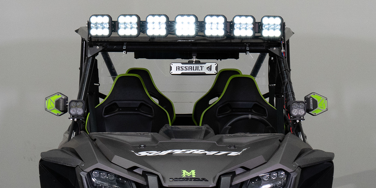
Build and install the seven-pod SS5 Sport Combo roof kit, with the original bracket, clip and wiring photographs.
Confirm the roof, cage and supplied kit
DD7917 White and DD7918 Yellow each contain seven SS5 Sport Combo pods, six links, two vehicle brackets, support and end-mount hardware, a DD4177 seven-pod connecting harness and a DD4123 relay harness. The current product page covers 2019–2025 Talon; the shared vehicle guide is titled 2019–2024. Low-profile or aftermarket roofs and aftermarket roll cages are excluded. Check windshield clearance at the lower mounts.
The shared guide mentions an eight-pod harness and other tiers. Use the seven-pod parts supplied with these two Sport kits; stop and confirm any mismatch before fitting. Prepare a 5 mm Allen key, 10 mm socket/wrench, 13 mm and 14 mm wrenches, Phillips screwdriver, trim tool and cable ties. Have a second person help lift the bar. Follow the vehicle electrical service procedure.
1. Fit both roof brackets
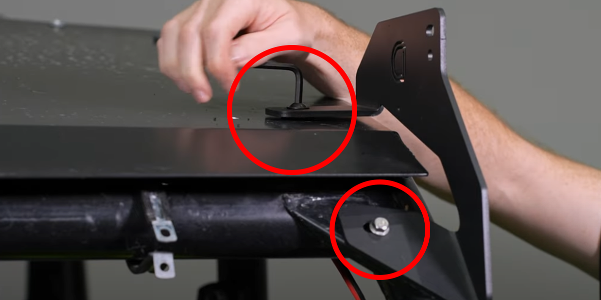
Remove the front roof bolt with a 5 mm Allen key and keep its washer. Refit the washer beneath the new upper bracket, start the supplied bolt loosely, then align and fasten the lower cage connection. Check windshield interference. Secure the lower hardware with 10 mm tools, then the upper bolt; repeat on the other side.
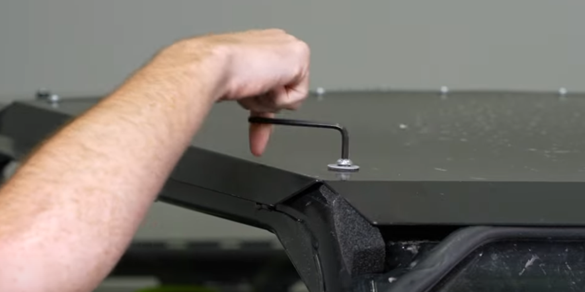
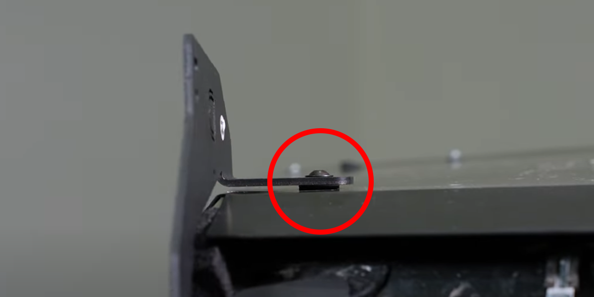
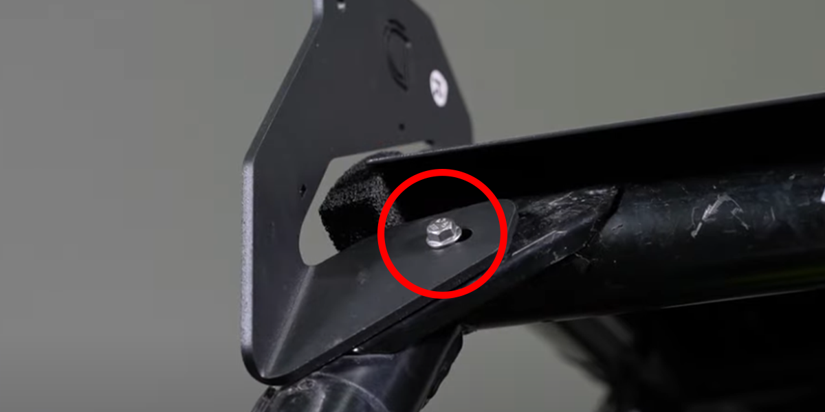
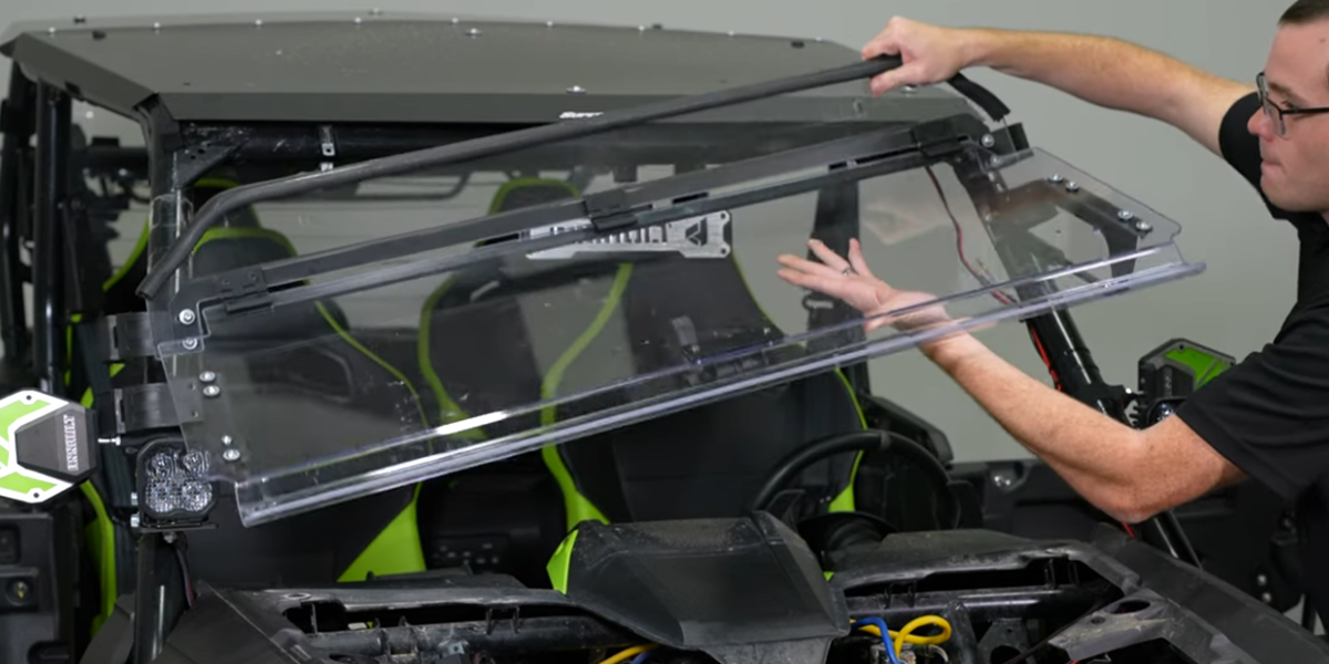
2. Link the seven pods and fit the supports
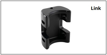
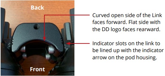
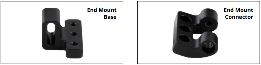
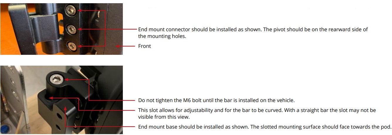
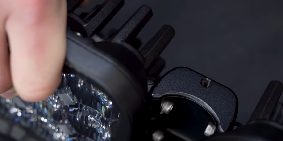
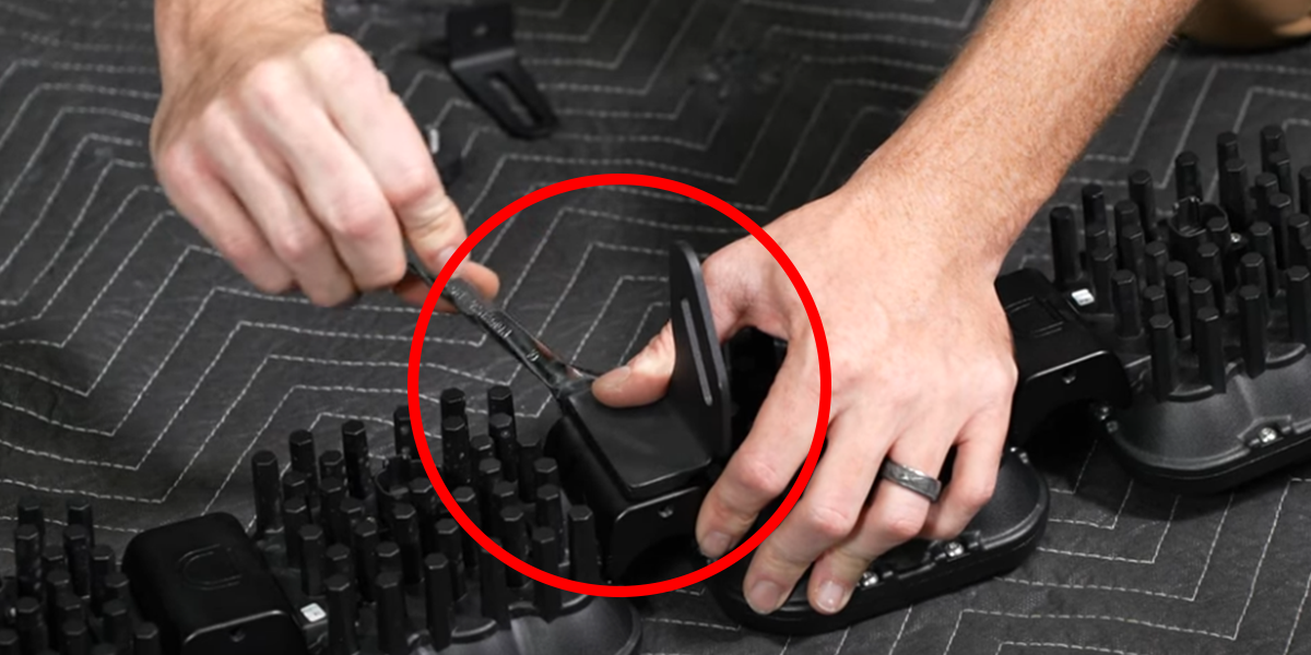
Use six CrossLinks between the seven supplied pods. The link’s curved open side faces forward and its DD logo faces rearward; align the slots with the pod indicator arrow. Assemble the end-mount bases and connectors following the original diagram. Set the vehicle end hardware at its first notch and secure the support mounts underneath with a 10 mm socket. The manufacturer recommends threadlocker on the long end bolts.
3. Lift and secure the roof assembly
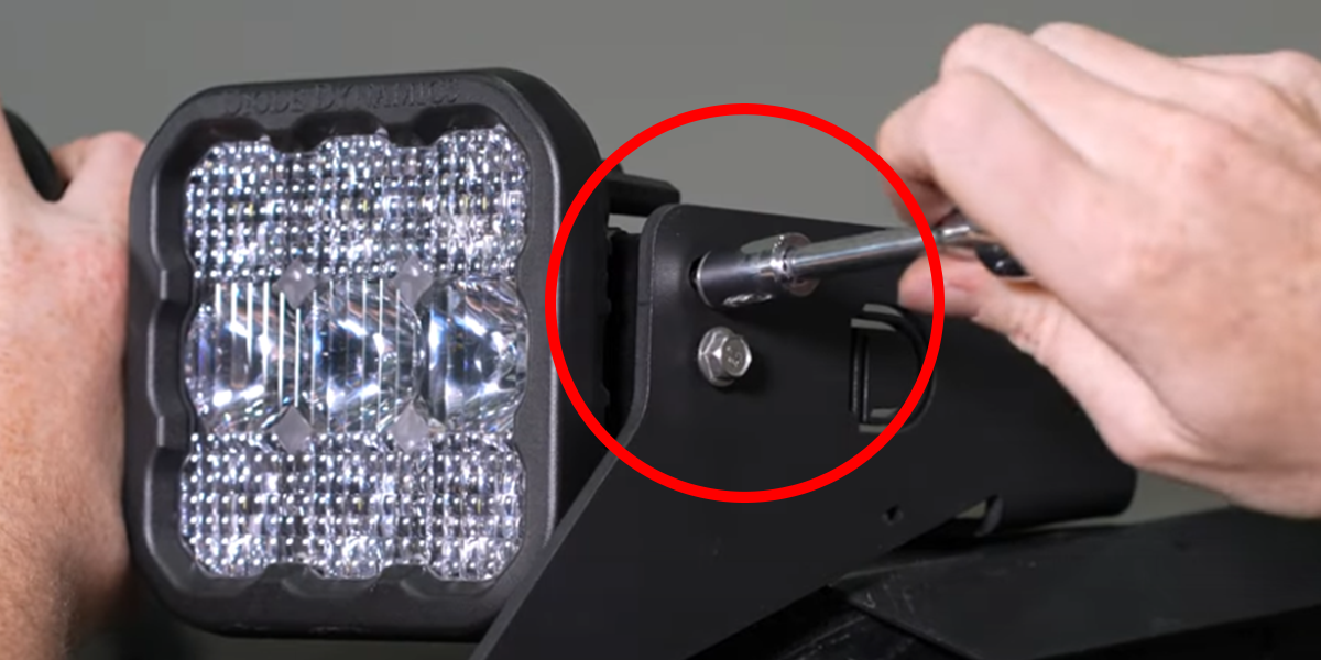
With a helper, lift the assembled bar onto the brackets and align the two upper attachment points. Install the supplied bolts at both ends. Set the support mounts against the roof and secure them using 13 mm and 14 mm wrenches. Check clearance before the final tightening; no vehicle-specific torque is stated in the source.
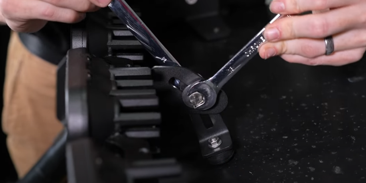
4. Connect the seven-pod harness
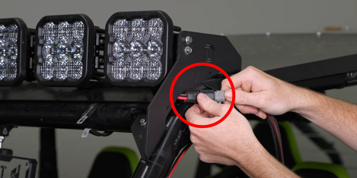
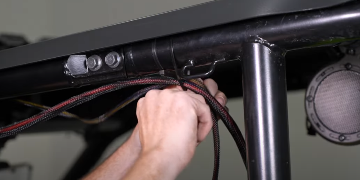
Connect the supplied DD4177 harness to all seven lamps, with its male end toward the driver’s side. Secure the harness behind the bar, clear of sharp edges and pinch points. The photograph is a shared routing example; its source’s eight-pod wording does not change this kit’s bill of materials.
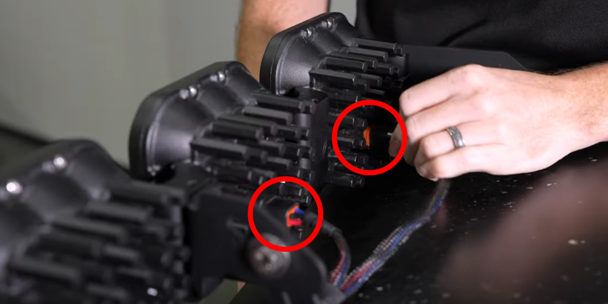
5. Access the battery and install the relay harness
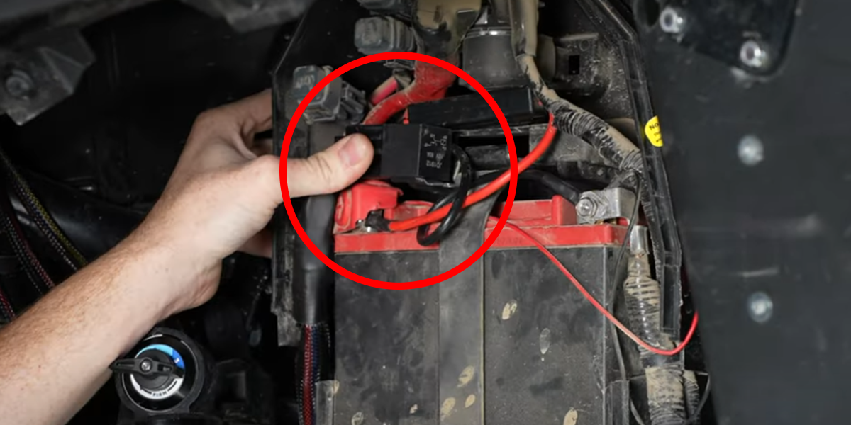
Release the three metal clips and remove the battery cover. Following the vehicle electrical service procedure, connect the relay harness’s identified positive and negative leads at the appropriate battery terminals. The source uses a Phillips screwdriver at these terminals. Secure the fuse and relay so the cover can be refitted without pinching or loading the wiring.
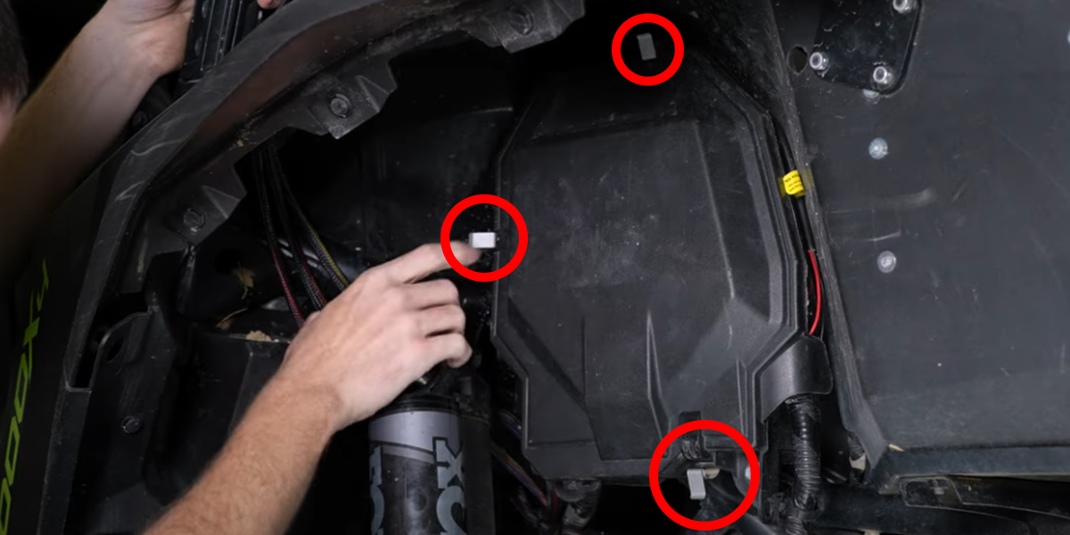
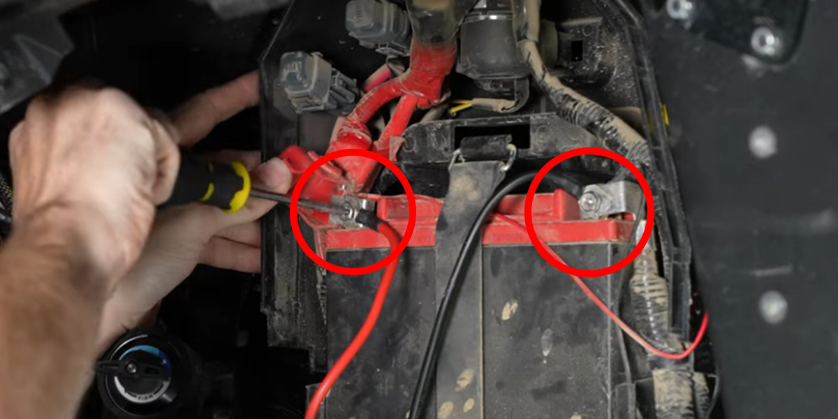
6. Route the switch and forward lead
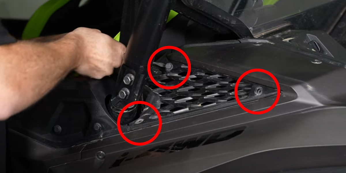
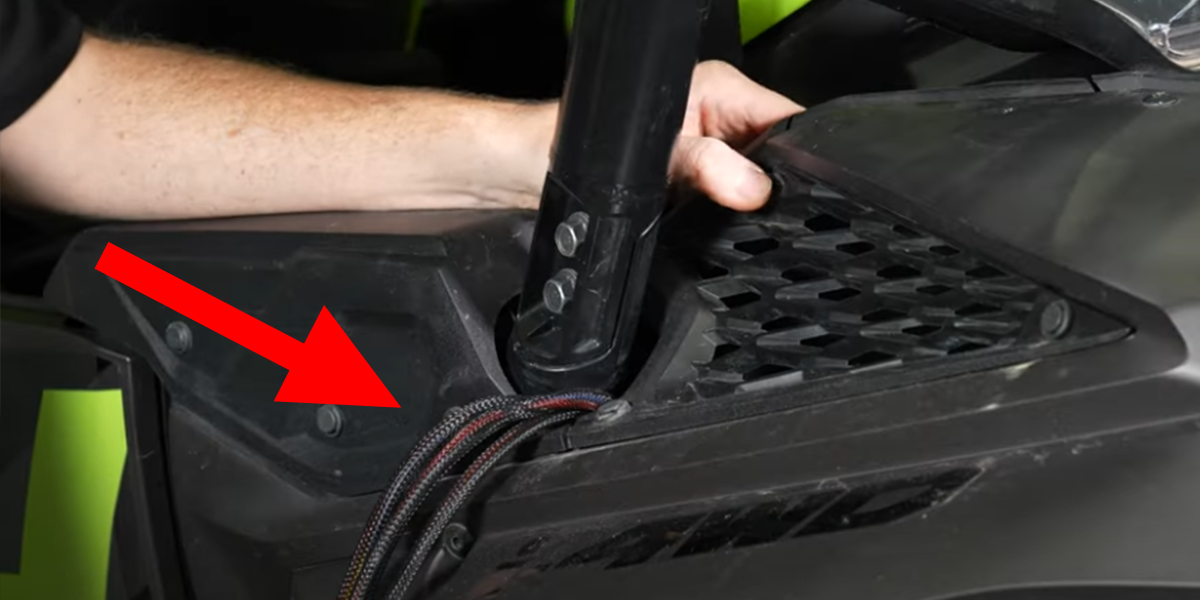
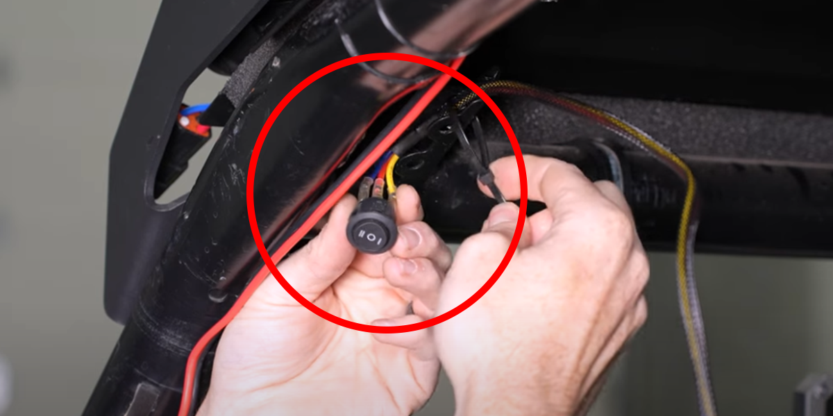
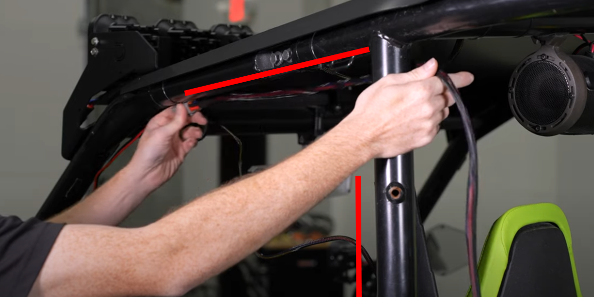
Release the three trim clips with a suitable trim tool. Route the switch and DT leads through the opening, refit the trim, and secure the included switch lead along the driver-side roll bar near the seat. Keep the controls accessible and the wiring clear of moving or hot parts.
Optional rectangular rocker switch
This accessory is sold separately. Disconnect the supplied toggle at its white inline connector, connect the compatible rocker in its place and fit it in a suitable blank. Ground its black ring-terminal lead for switch illumination. The diagram below describes this switch harness, not the pod connector pinout.
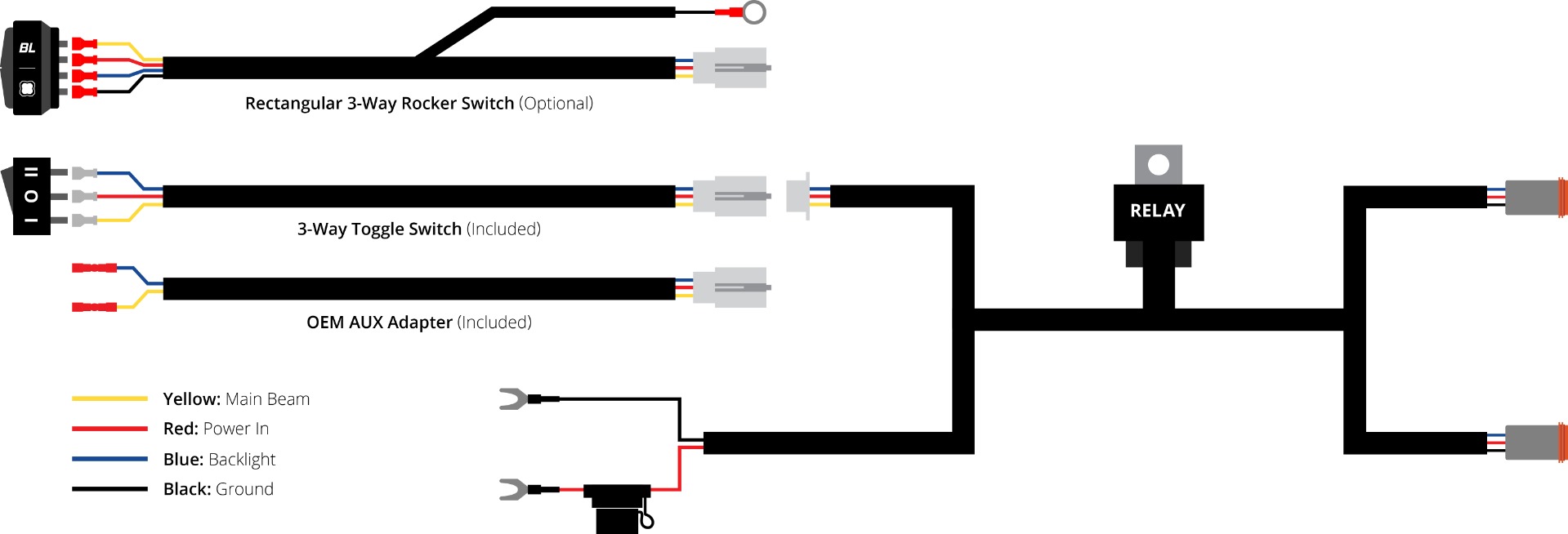
7. Connect, test and finish
Route the DT lead beside the switch lead and connect it to the CrossLink harness. Test the main beams and separate backlights, aim the bar for its intended use, secure loose wiring and reinstall the removed panels. Confirm the roof, cage and windshield remain clear throughout normal operation.
White-kit backlight colours
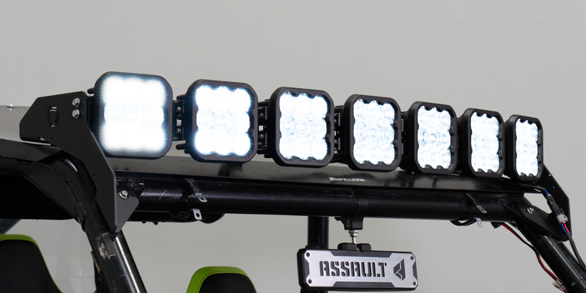
These instructions apply to the White main-beam kit. Yellow-lens pods have fixed Amber backlighting. With backlight power off, cycle it on and off three times within three seconds, spacing the on commands about one second apart. Continue at that pace to move through the colours. Leave the chosen colour on for five seconds to save, then switch off.
If the linked White pods become unsynchronized, enter programming and cycle through the entire colour sequence twice, at least sixteen cycles. All pods return to White. Leave them on for five seconds to save, then select the desired colour again.
Original instructions and installation video
Refer to the manufacturer vehicle guide, CrossLink assembly instructions and SS5 pod instructions. These current originals are web guides; no vehicle PDF is supplied. Photographs and footage can show other lighting or kit revisions; use the exact seven-pod Sport contents above.