

POLARIS RZR XP · SS3 / SS5
RZR XP A-pillar light installation guide
Fit the vehicle brackets and spacers, assemble your SS3 or SS5 pods, route the supplied four-pin harness and aim the lights.
Match the kit and vehicle
This guide covers SS3 kits DD8080–DD8083 and SS5 kits DD8084–DD8087. The vehicle application is 2019–2023 RZR XP1000 and 2019–2021 RZR XP Turbo / Turbo S. Windshields and aftermarket cages can interfere; check clearance before starting.
Have a 15 mm socket, 10 mm socket or wrench, T25 Torx driver, 5/32-inch Allen wrench, 13 mm wrench, trim tools and zip ties ready. Work on a cool, secure vehicle and follow its battery-isolation instructions. The brackets use existing A-pillar fasteners. An optional rectangular rocker switch is a separate part.
VEHICLE STEPS 1–2
Fit and level the A-pillar brackets
Remove the lower A-pillar bolt with a 15 mm socket. Refit it loosely with the supplied spacer. Remove the upper bolt and position the driver-side bracket over the lower bolt.
Place the remaining spacer between the pillar and bracket at the upper mounting point. Pass the upper bolt through, level the bracket and secure the hardware. Repeat on the passenger side. Check windshield and cage clearance before proceeding; use the vehicle service instructions for fastener requirements.
VEHICLE STEP 3
Route power, ground and the switch lead
Use the DD4093 heavy-duty dual-output four-pin harness supplied with the kit. At the factory bus bar, remove the positive and negative terminal hardware with a 10 mm tool and connect the matching harness leads. The manufacturer shows the relay mounted at the bus-bar area with a T25 screw. If using the battery connection route, remove the driver seat for access and connect at the designated battery terminals using a 10 mm tool.
Route the two lamp outputs to the A-pillars and the switch lead to the chosen control position. Keep all wiring clear of hot parts, sharp edges, pedals and moving components. Protect and secure each pass-through.
Optional rectangular rocker switch
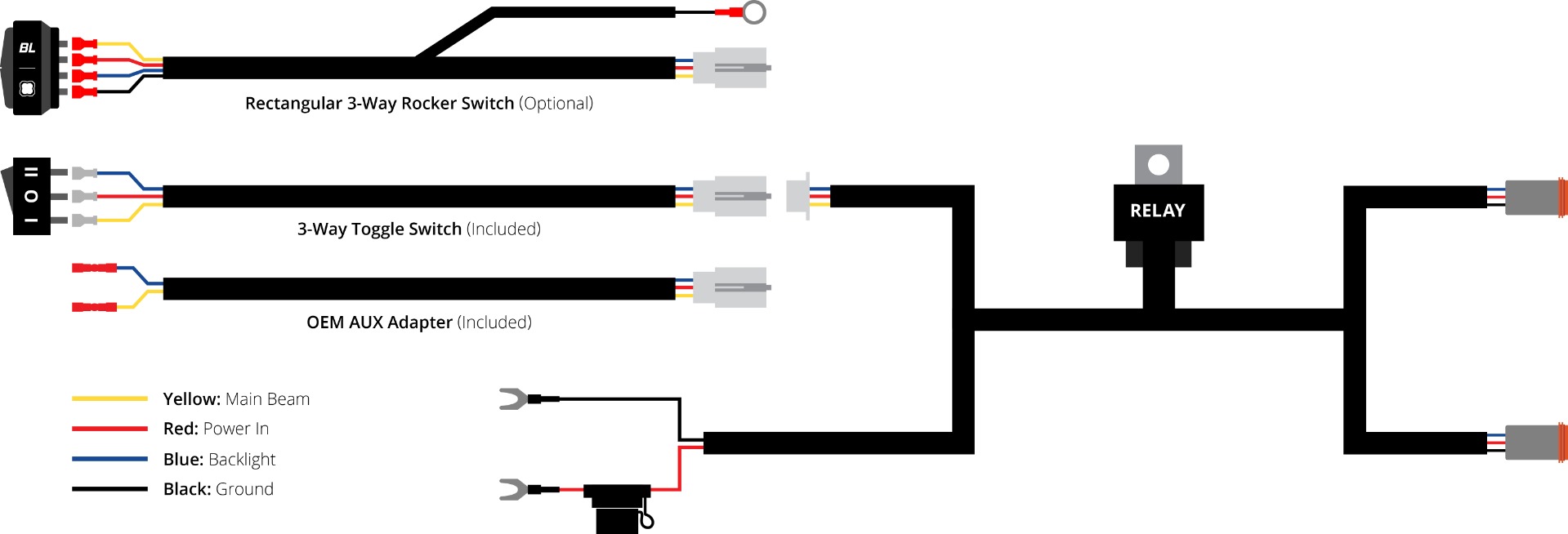
The supplied harness has its own switch. To use the separately purchased rectangular rocker shown below, disconnect the white connector on the harness switch lead and connect the matching rocker-switch lead. Fit the switch in a suitable factory blank and connect its black ring terminal to ground for switch illumination. This diagram identifies the optional switch terminals; it is not the pinout for the kit’s four-pin lamp connectors.
VEHICLE STEP 4
Assemble the bracket for your pod family
SS3
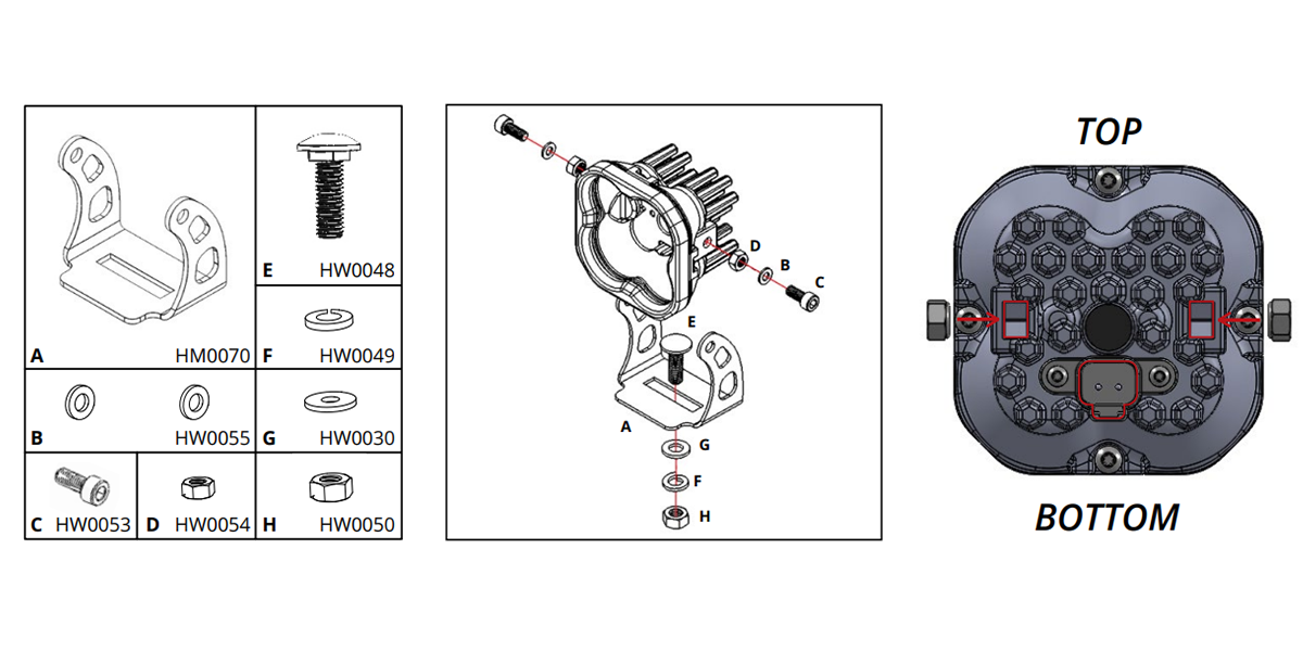
Insert the supplied nuts into the SS3 mounting slots with the nylon locking rings facing inward. Fit the U-bracket and use the supplied Allen screws and washers, leaving enough movement for final aiming. Keep the pod upright in the orientation shown.
SS5
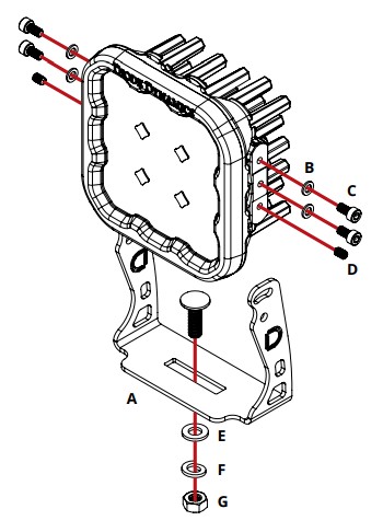
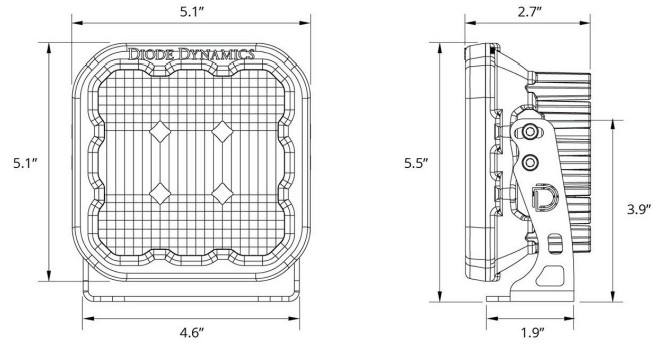
Use the SS5 hardware and U-bracket shown below. Place the locking nuts in the pod slots, align the bracket and start the mounting screws and washers. Leave the pod adjustable until it is mounted and aimed. Check the larger SS5 housing and bracket against your windshield and cage before tightening.

VEHICLE STEPS 5–6
Mount, connect, aim and test
Connect each pod to its matching sealed harness output. Fit the pod U-bracket to the vehicle bracket with the carriage bolt, washers, lock washer and nut supplied with the kit. Use a 13 mm wrench on the mounting hardware while leaving adjustment for aiming.
Secure the wiring with zip ties, restore power safely and test the main lights and accent backlights separately. Aim the pods for useful trail coverage without glare across the vehicle or toward other users. Tighten the pod and mounting hardware with the Allen wrench and 13 mm wrench. Recheck wiring and mechanical clearance.
The main beam is fixed White or Yellow by the selected SKU. These are auxiliary off-road lights; a pod’s individual beam designation does not establish road approval for the complete UTV installation.
Main beams and backlights use different controls
SS3 uses a fixed Amber accent backlight. White-lens SS5 offers eight selectable backlight colours; Yellow-lens SS5 has Amber only. Backlight programming does not change the White or Yellow main beam.
White-lens SS5 colour programming
Switch the backlight on and off three times within three seconds, about one second per cycle, to enter programming. Cycle the backlight to the desired colour, leave it on for five seconds to save, then switch it off. To reset, cycle through the colours twice—at least sixteen cycles—until White appears, leave it on for five seconds and switch it off. Use this procedure only for the eight-colour White-lens SS5.
Watch the RZR XP installation
Original instructions
RZR XP vehicle installation article · SS5 pod assembly and backlight article · Original SS3 assembly PDF
The generic pod references show mounting hardware. Their older three-pin wiring and output tables do not describe this DD4093 four-pin vehicle kit; use the supplied kit harness and matching connectors.