

POLARIS RZR XP · SS3 / SS10
RZR XP grille light installation guide
Remove the original grille, choose the correct power route, then follow the two-pod SS3 or single-bar SS10 assembly branch.
Match the kit and vehicle
The SS3 kits cover 2019–2023 RZR XP1000 and 2019–2021 RZR XP Turbo / Turbo S. The SS10 kit is listed for 2019–2023 Polaris RZR XP; confirm the exact model and grille before installation. These instructions do not extend either kit to 2024 or later vehicles.
SS3 uses two pods, the matched replacement grille, DD4104 four-pin harness and DD4100 two-way splitter. SS10 uses one bar, its matched grille and DD4104 harness connected directly to the bar. The optional rectangular rocker switch is separate.
Have T25, 10 mm and 13 mm tools, the supplied pod-assembly tools and zip ties ready. Work on a cool, secure vehicle and follow its battery-isolation instructions. The final mounting uses six self-tapping screws; plan that step before removing the original grille.
1–3. Remove the grille and lower cover
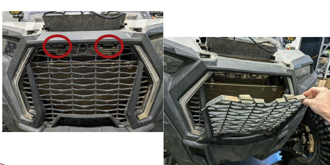
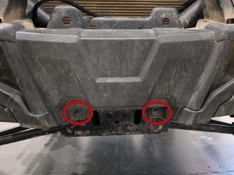
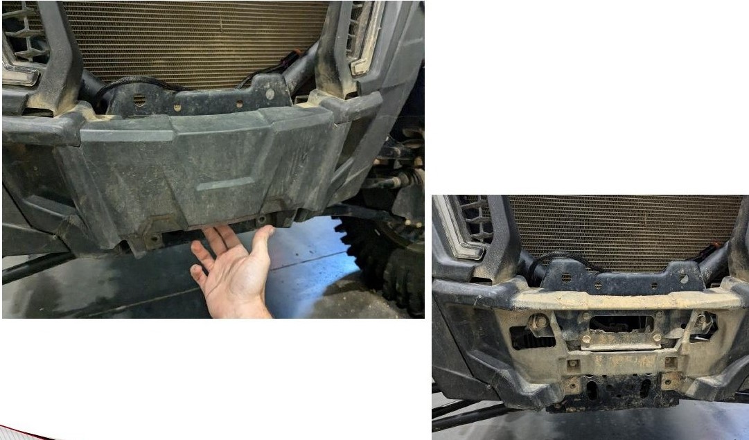
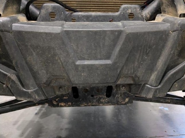
Press the two upper retaining tabs and remove the original grille. Remove the two lower bumper-cover screws with a T25 tool, then lift away the lower cover to expose the mounting area.
4–7. Choose the power route
Factory bus bar
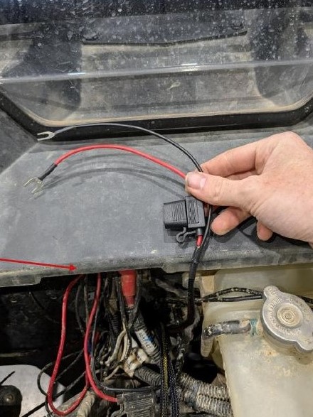
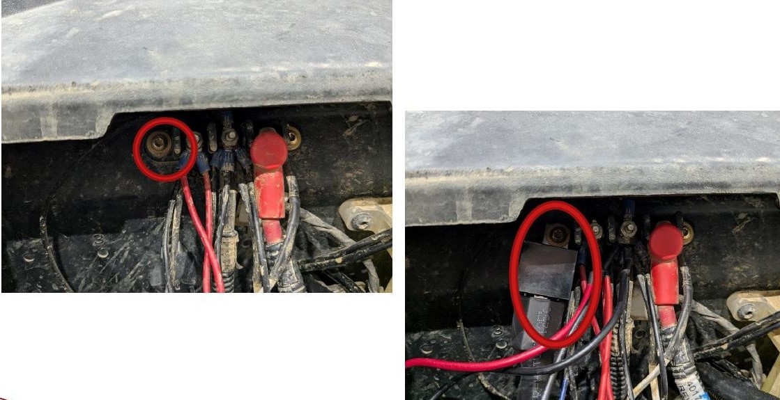
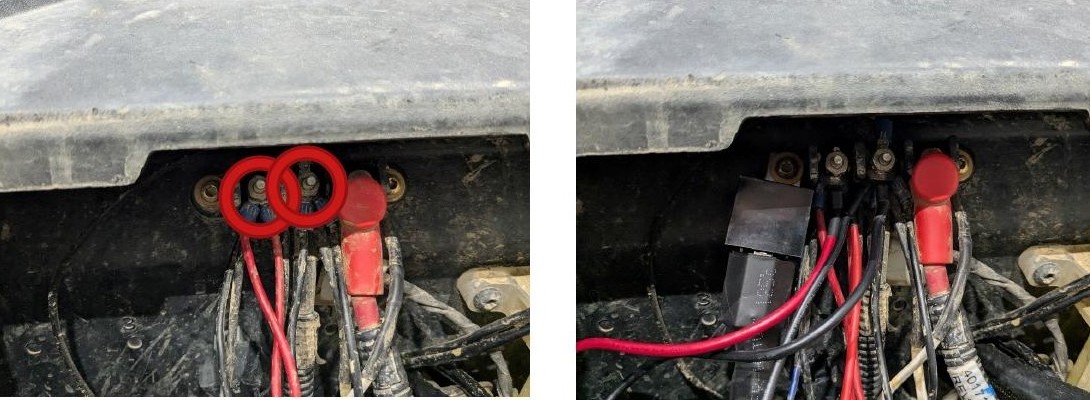
If the vehicle has the factory bus bar, route the switch lead through the factory firewall opening and into the cabin. Mount the relay beside the bus bar using the indicated T25 screw. Use a 10 mm tool to connect the matching positive and negative harness leads at the bus bar.
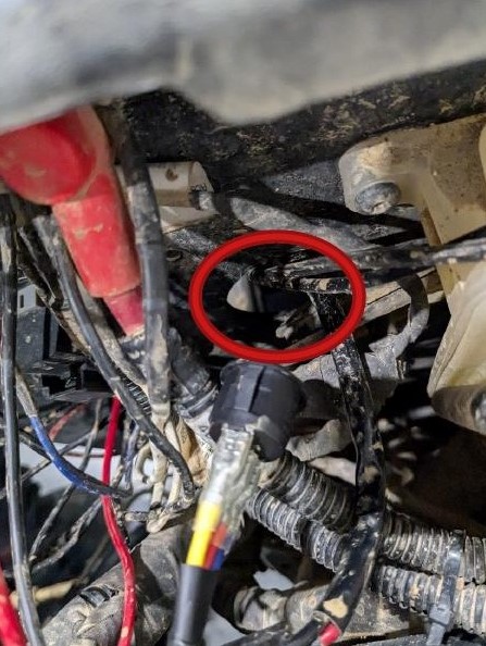
Alternative: connect at the battery
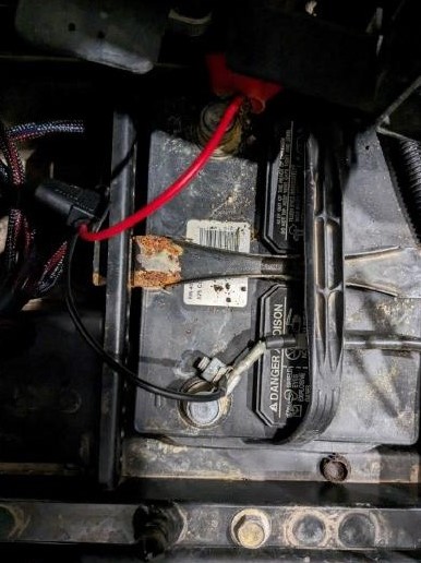
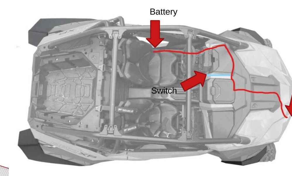
On vehicles without the bus bar, remove the driver seat for battery access. Use a 10 mm tool for the matching battery-terminal connections. Route the harness forward alongside the driver-side door sill and up behind the dash as shown. Secure it clear of the seat mechanism, pedals, sharp edges and moving parts.
8–9. Route the lamp lead and switch
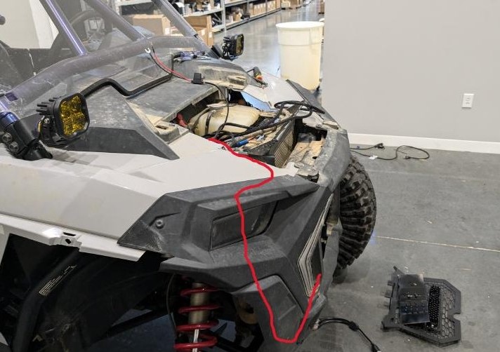
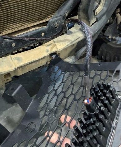
Route the DT lamp lead behind the radiator and out through the grille opening, keeping it clear of heat, sharp edges and moving parts. Connect the supplied switch, but leave its final mounting until testing is complete.
For the separately purchased rectangular rocker, disconnect the white inline connector on the harness switch lead and connect the matching rocker lead. Its black ring terminal provides the ground for switch illumination. That switch connection is separate from the four-pin lamp connectors.
10. Assemble the branch for your lights
Two SS3 pods
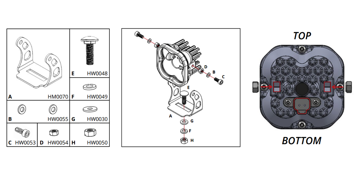
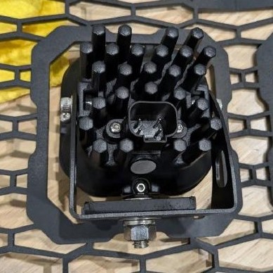
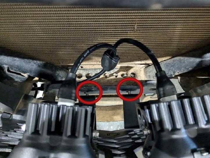
Assemble each pod’s U-bracket using the supplied locking nuts, screws and washers, keeping the pod upright as shown. Position the U-brackets beneath the grille mounting tabs. Use the supplied carriage bolts, washers, lock washers and nuts with a 13 mm tool. Centre each pod and leave adjustment for final aiming.
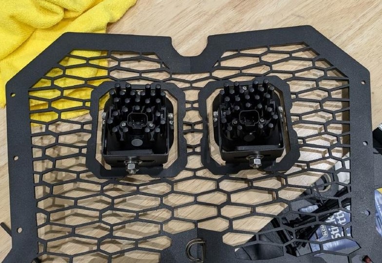
Single SS10 bar
Insert the SS10 into the front of its matching grille. Start the two supplied mounting bolts with a 10 mm tool and leave the bar adjustable for aiming. The SS3 U-brackets and splitter are not used for this branch.
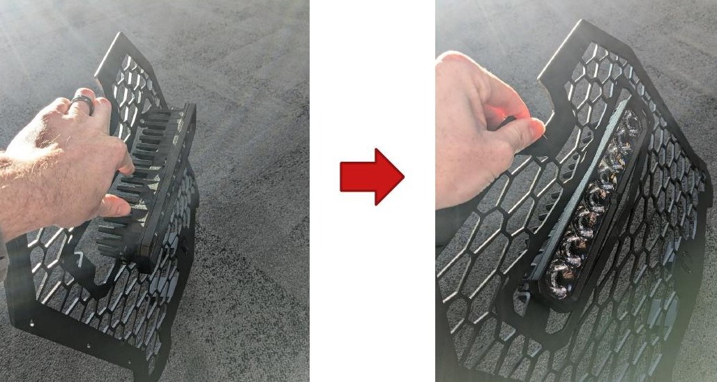
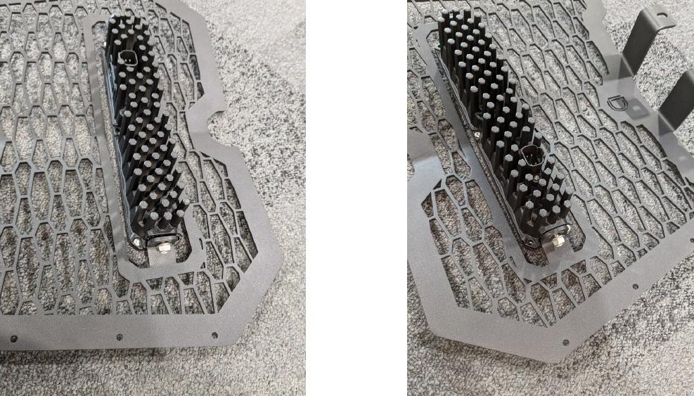
11. Connect the lamps
SS3
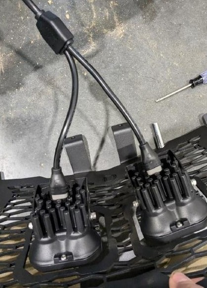
Connect the two-way splitter to the main harness, then connect one splitter output to each pod.
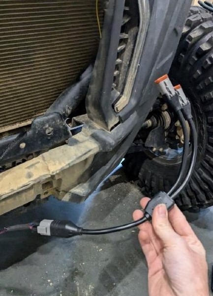
SS10 direct connection
Connect the single DT harness output directly to the SS10 bar. Fully seat the matching sealed connector; do not adapt the older three-pin wiring diagrams to this four-pin kit.
12–15. Secure the grille and refit the cover
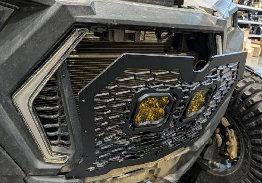
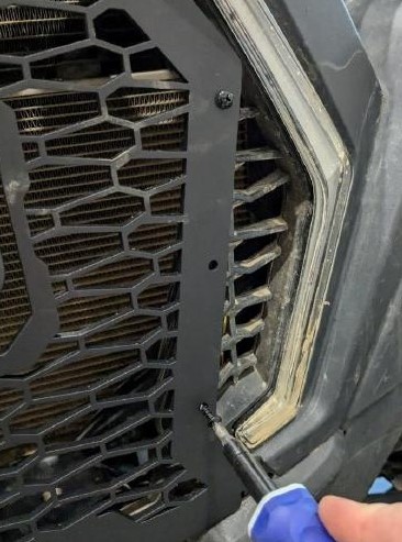
Place the assembled grille into the opening and align the lower mounting holes. Loosely fit the two lower bolts and nuts. Tighten the lower hardware, then install the six self-tapping screws around the grille, alternating sides and avoiding overtightening.
Refit the lower bumper cover with its two original T25 screws.
16. Test, aim and secure
Restore power safely. Test the main beam and accent backlight separately, aim the lights for useful trail coverage, and tighten the lamp mounting hardware. Secure excess wiring and recheck clearance before using the vehicle.
SS3 has a fixed Amber accent. White SS10 offers eight backlight colours with a startup sequence except in Amber mode; Yellow SS10 has Amber only and no startup sequence. Backlight colour does not change the fixed White or Yellow main beam. Use the controls supplied with the exact kit.
Watch the grille installation
Original instructions
Original vehicle installation article · Original SS3 assembly PDF
The generic SS3 PDF is a mechanical assembly reference. Its older three-pin electrical diagrams and output tables do not describe the DD4104 four-pin vehicle harness. Follow the exact kit connections shown above.