

BTS installation guide · BAF071
2021–2023 Ford F-150 Morimoto 4Banger fog installation
Follow the bumper, bracket and wiring steps for your factory fog-light type. The kit fits standard F-150 factory fog-light openings; it does not fit Raptor.
Before you begin
Work with the vehicle secure and support the bumper during removal. Protect painted surfaces and retain factory hardware by location. Use professional installation if you are not comfortable removing the front bumper or working with battery-powered wiring. Follow Ford’s service guidance for factory fastener torque; this guide does not invent torque values.
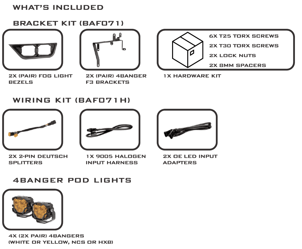
Have a plastic trim tool, ratchet, 7mm, 8mm, 10mm, 13mm and 21mm sockets, T20/T25/T30/T50 Torx bits and a 17mm wrench available. Check the supplied hardware against the kit before disassembly.
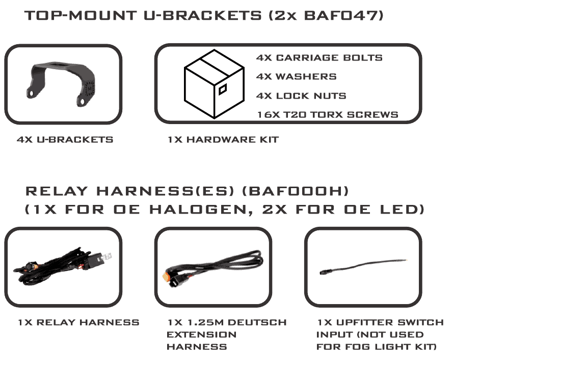
The complete LED kit has two BAF000H relay harnesses; the halogen kit has one. The common adapter pack includes pieces that your installation will not use. The upfitter-switch input supplied with the relay harness is not used in this factory-fog installation.
Morimoto’s 2021–2023 F-150 4Banger fog installation video.
Check the supplied parts
Assemble the bezels and pods
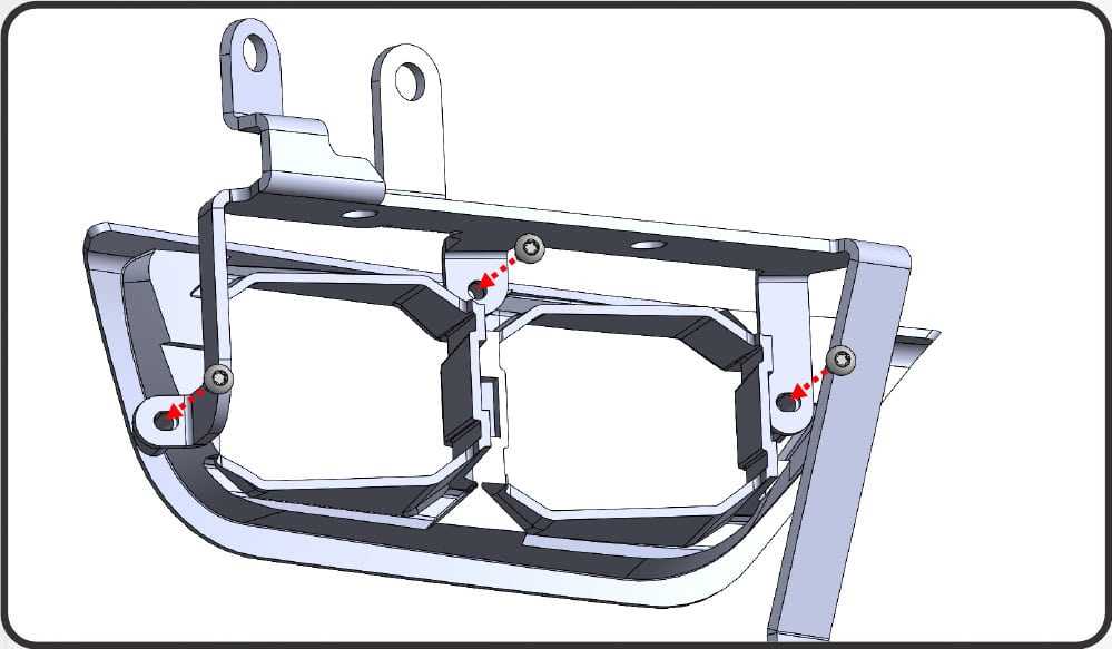
- Attach each vehicle bracket to its bezel with three supplied T 25 screws.
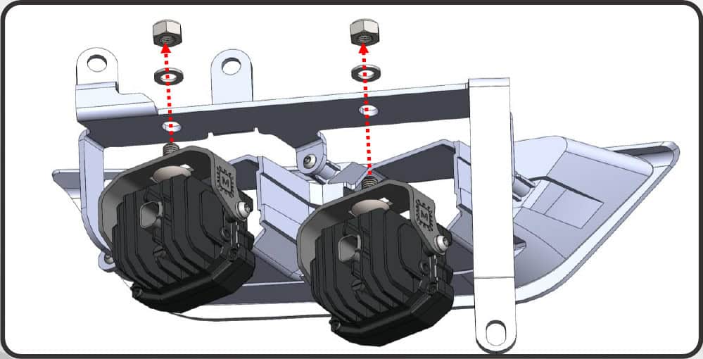
- Fasten a U-bracket to each 4 Banger using the supplied T 20 screws. Mount the U-brackets to the vehicle bracket with the carriage bolts, washers and 17 mm lock nuts.
- Repeat the assembly for the other side.
Remove the trim and grille
- Raise the hood.
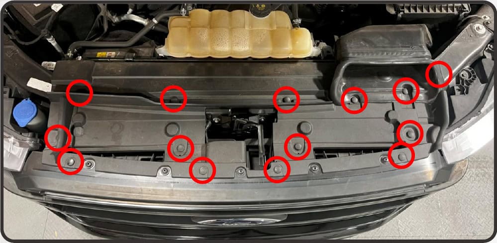
- Remove the 14 push clips holding the radiator cover, then lift the cover off.
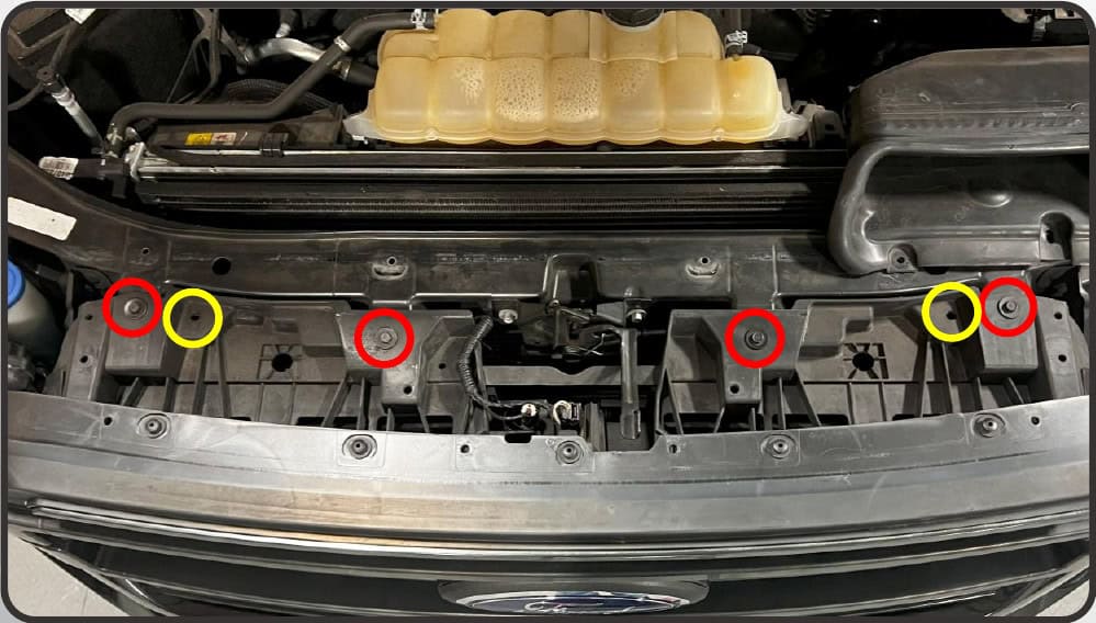
- Remove the four 10 mm bolts and two push clips securing the top of the grille.
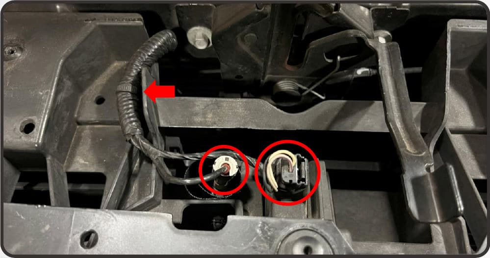
- If fitted, disconnect the grille wiring and camera-washer fitting. Release the clip holding that harness to the grille.
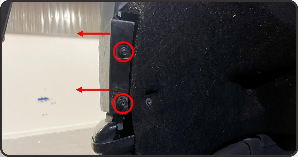
- At each front wheel well, remove the two 7 mm screws holding the bumper trim. Carefully release the trim’s outer end from the fender.
- Pull the bumper trim forward to release it from the grille, then set it aside.
- Remove the two 8 mm screws at the grille’s lower corners, one per side. Pull the grille forward and set it aside.
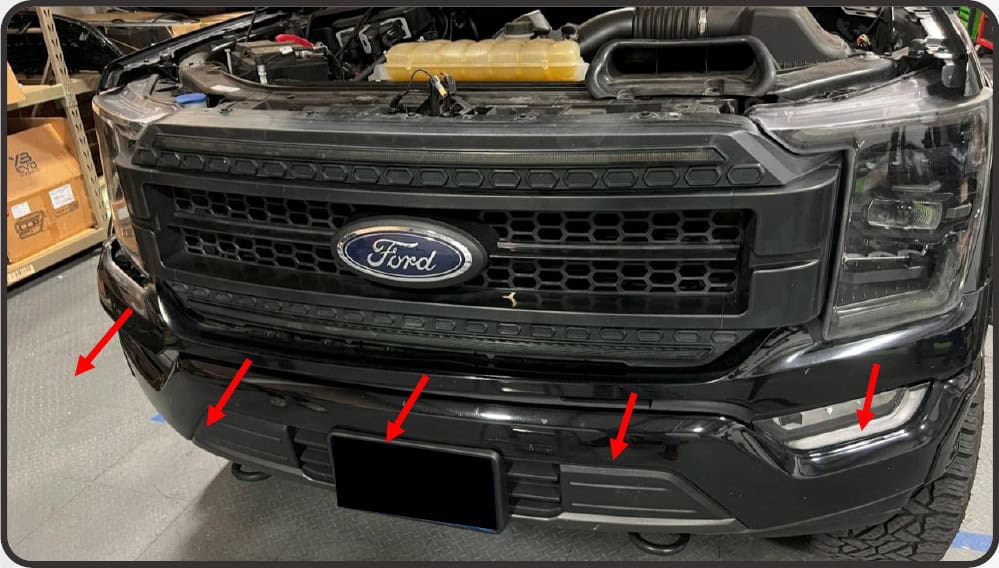
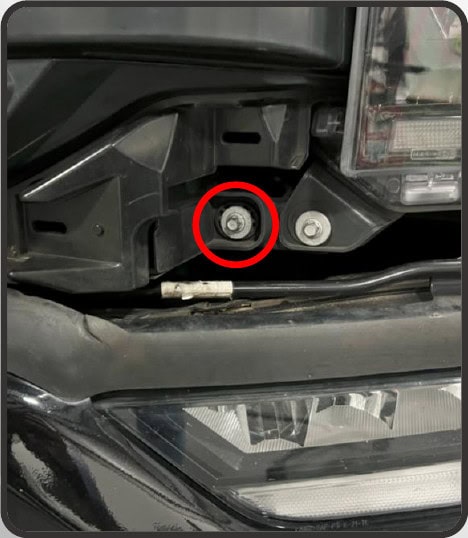
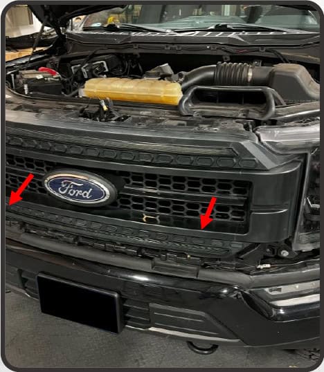
Remove the bumper and factory fogs
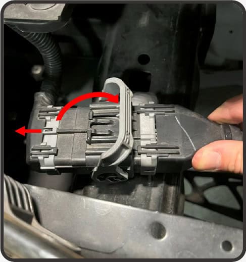
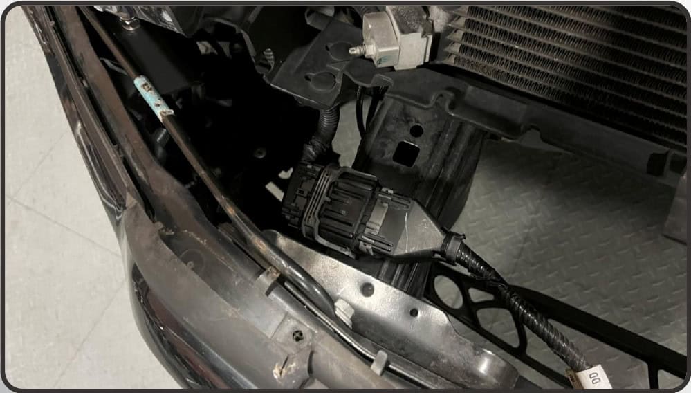
- Unplug the front-bumper harness: press the black lock, rotate the grey latch back and separate the connector.
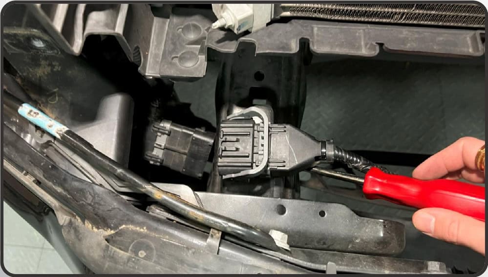
- Release the bumper-harness connector from its clip on the front frame rail.
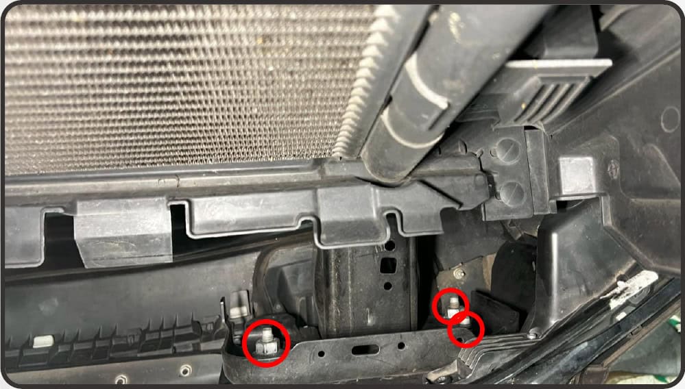
- Support the bumper and remove its six 21 mm retaining nuts, three at each frame rail.
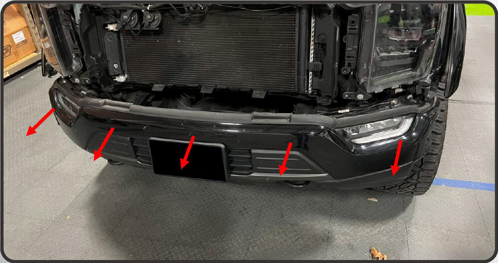
- Move the bumper straight forward off the truck. Place its painted face on a soft, padded work surface.
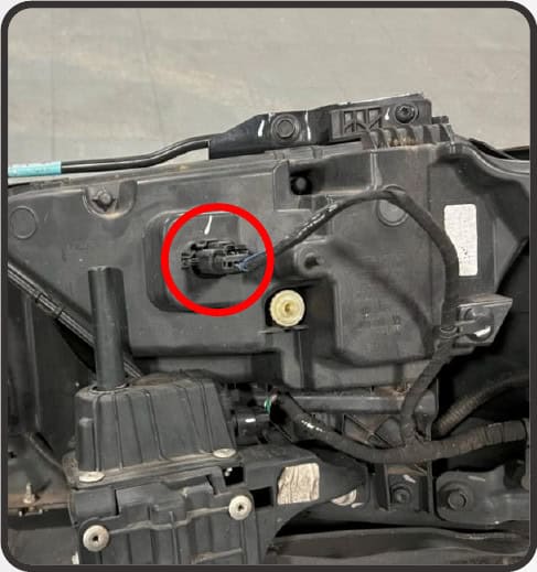
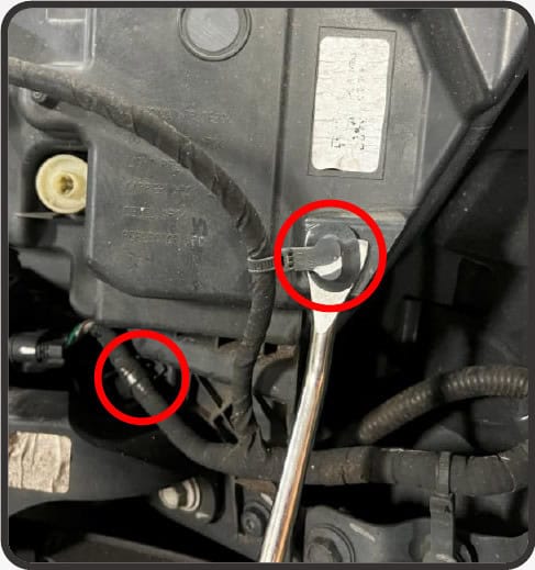
- Unplug each factory fog light. Release the one or two wiring clips behind each fog-light assembly.
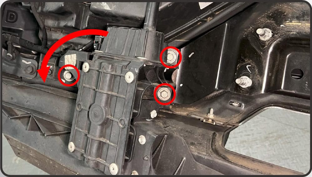
- If the truck has an active front air dam, remove its six 13 mm bolts, three per side, and lean the assembly back out of the way.
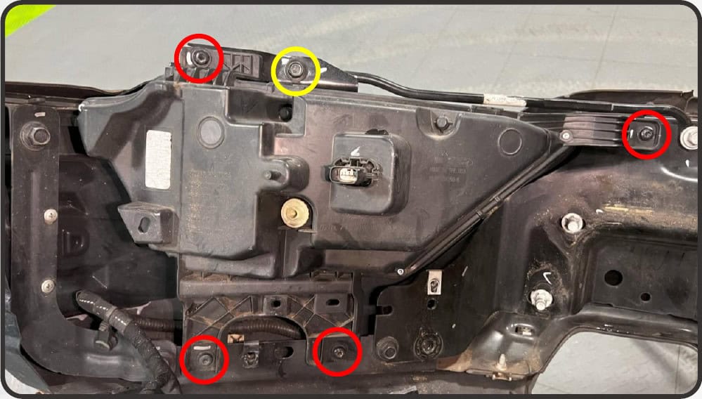
- Remove the four T30 screws holding each factory fog assembly and the 13 mm bolt above it. Lift out the fog assembly and repeat on the other side.
- Where fitted, move the active air dam back into position and reinstall the two lower bolts on each side.
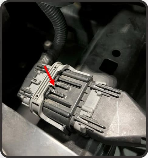
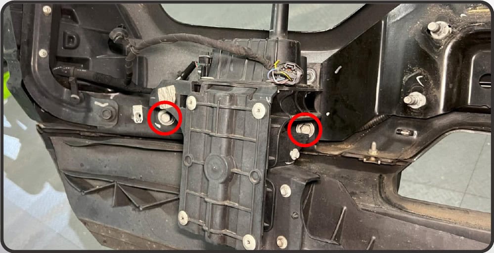
Mount the new fog assemblies
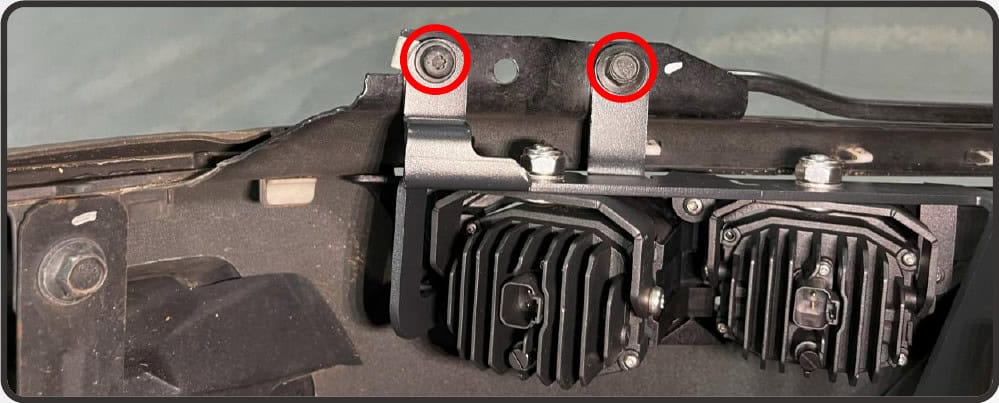
- Set the new 4 Banger assembly into the bumper opening. Secure its upper mounts with the two factory bolts removed from above the original fog light.
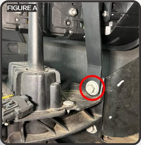
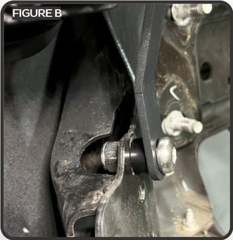
- With an active air dam, reinstall the upper factory bolt through the fog bracket’s lower arm so it secures both pieces. Without an active air dam/threaded clip, fit the supplied spacer between bracket and bumper, then secure it with the supplied T 30 bolt and nylon lock nut.
- Fit the second assembly in the same way.
Route the harnesses and refit the bumper
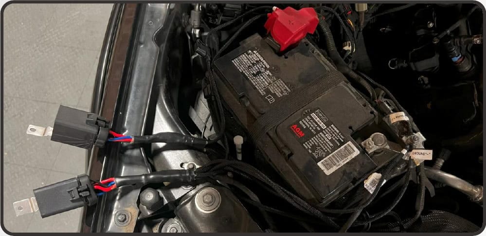
- Lay the relay harness or harnesses beside the battery. Choose an upright relay position with the wires exiting downward and enough reach for the positive and negative battery terminals.
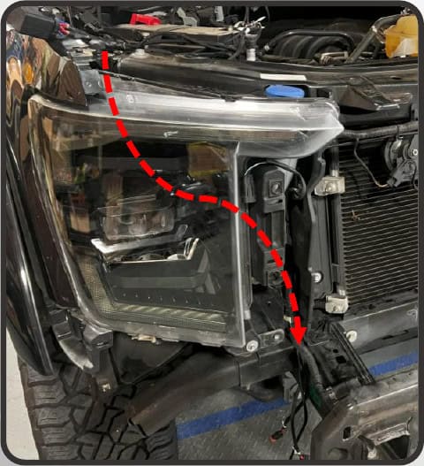
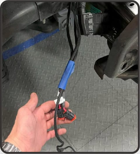
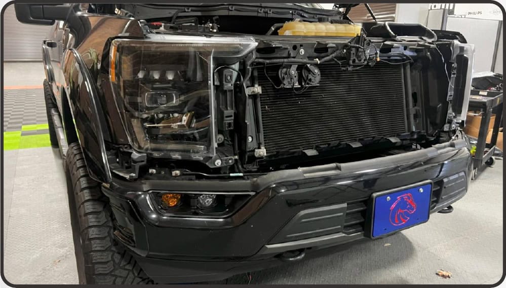
- Route each harness input and outputs behind the passenger headlight and forward of the frame. For LED kits, keep each harness’s input and outputs grouped so the two sides do not become mixed.
- Reinstall the bumper and secure it with the six original 21 mm nuts.
- Reconnect the bumper wiring and secure its connector to the frame-rail clip.
Choose the correct wiring path
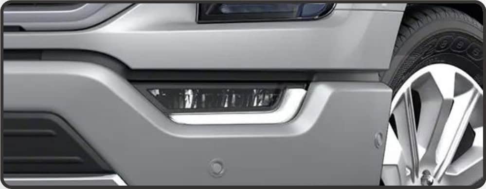
- Identify the original fog-light type below. Follow only the matching wiring path.
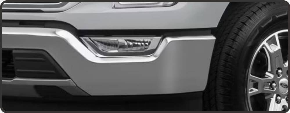
Factory halogen fog-light wiring
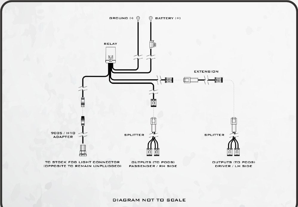
Use this section only for factory halogen fog lights. One relay drives all four pods through the two splitters.
- For factory halogen fogs, connect the supplied extension to one relay output and add an output splitter at its end. Route it behind the bumper to the two driver-side pods.
- Fit the other splitter to the remaining relay output and connect it to the two passenger-side pods.
- Connect the 9005/H 10 input adapter to the relay-harness input and the passenger-side factory fog connector. The opposite factory connector remains unplugged as shown in Morimoto’s diagram.
- Connect the harness terminal marked Battery (+) to the positive battery post.
- Connect the Ground (-) terminal to the negative battery post. Continue to the shared finishing steps.
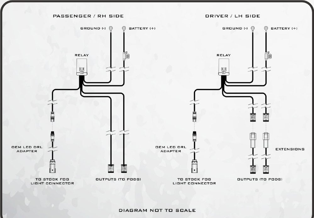
Factory LED fog-light wiring
Use this section only for factory LED fog lights. Keep the left and right relay circuits separate.
- For factory LED fogs, connect the two outputs of the passenger-side relay harness to the two passenger-side pods.
- Connect an OEM LED input adapter to that harness and the passenger-side factory fog connector.
- Fit one extension to each output of the driver-side relay harness. Route both behind the bumper and connect them to the two driver-side pods.
- Fit the remaining OEM LED input adapter to the driver-side harness. Route its input behind the bumper and connect it to the driver-side factory fog connector.
- Connect both terminals marked Battery (+) to the positive battery post.
- Connect both Ground (-) terminals to the negative battery post.
Test, secure and aim
- Operate the lights from the truck and check that all intended functions work.
- Secure each relay in the chosen engine-bay position near the battery.
- Secure loose wiring away from moving parts and high-heat components.
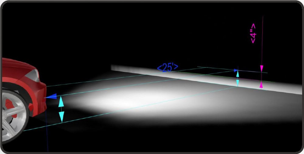
- Aim the fog lights on level ground 25 feet from a wall. Measure the lamp-center height. At the wall, the top of the beam should be 4 inches lower than that height. Once aligned, tighten the pod-to-bracket screws.
- With the lights tested, secured and aimed, reinstall the remaining front-end parts in the reverse order of removal.
Ready for the next step?
Choose your 4Banger fog kit · Explore the F-150 lighting range