

BTS installation guide · Jeep lighting
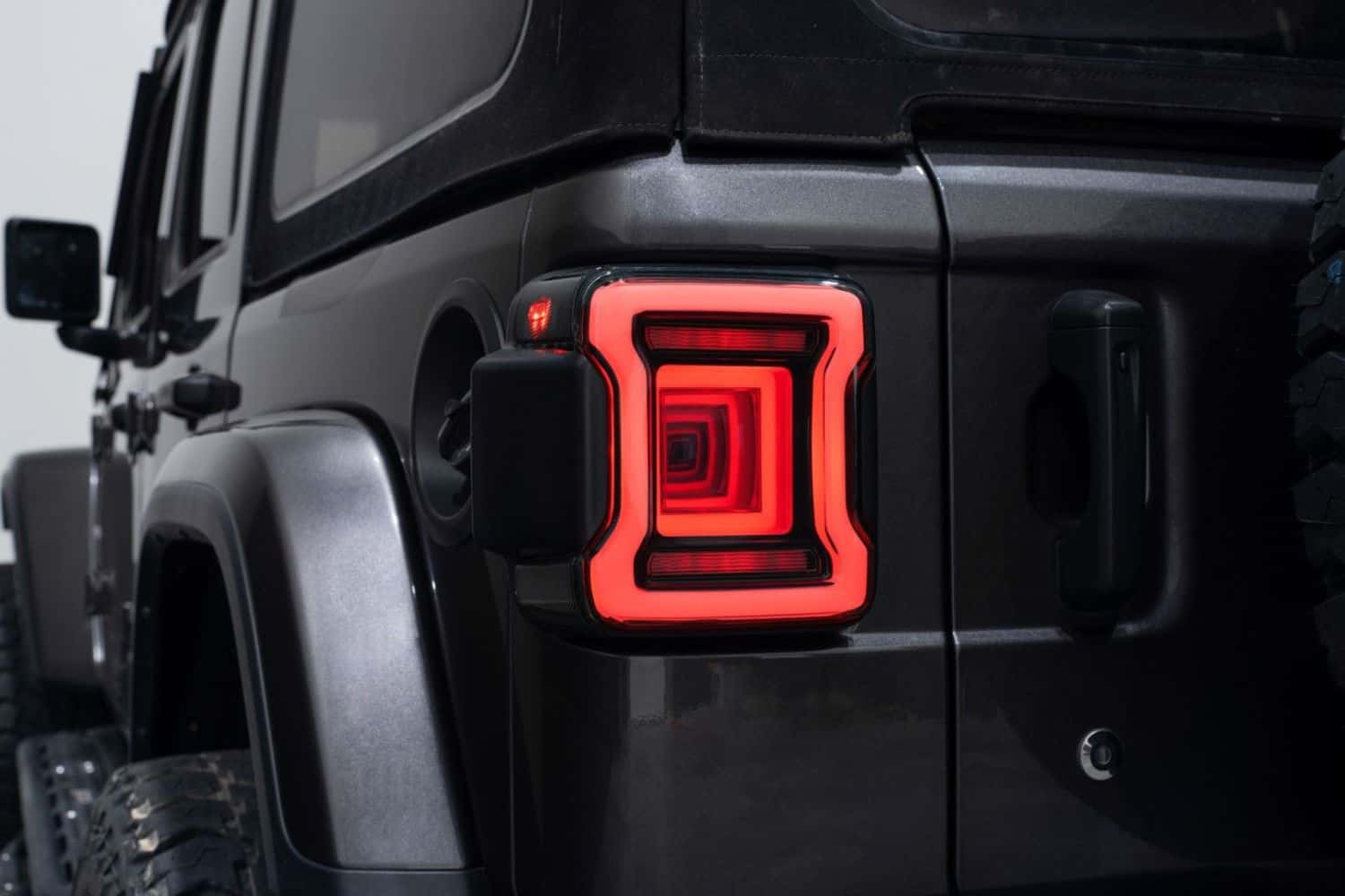
Jeep JL FORM Tail Light Installation
Install FL0013/FL0014 tail lights, transfer the original blind-spot modules and connect the optional sequential amber turn-signal lead.
Use this guide for the FORM FL0013/FL0014 pair listed for 2018–2023 Wrangler JL. The rear lighting functions connect at the original lamp connector; the separate front-signal connection enables the sequential amber turn signal.
Prepare a trim tool, Phillips screwdriver, 10 mm and 8 mm sockets. The optional terminal work also uses needle-nose pliers and a small pick. Park securely, switch the lighting off and protect each lamp on a soft surface.
Plan the installation
Choose the rear-only or sequential connection
Without the extra signal lead, the lamp flashes as a whole for the turn signal, as described by FORM. The added harness connects to the front turn-signal circuit for the separate sequential amber function.
Remove the original lamps
1. Access the mounting bolt
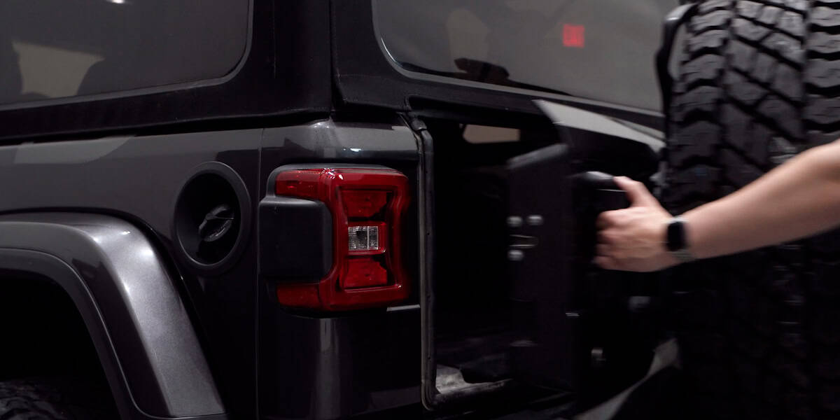
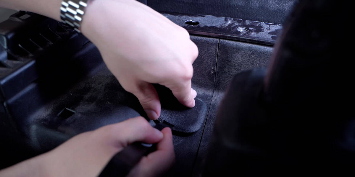
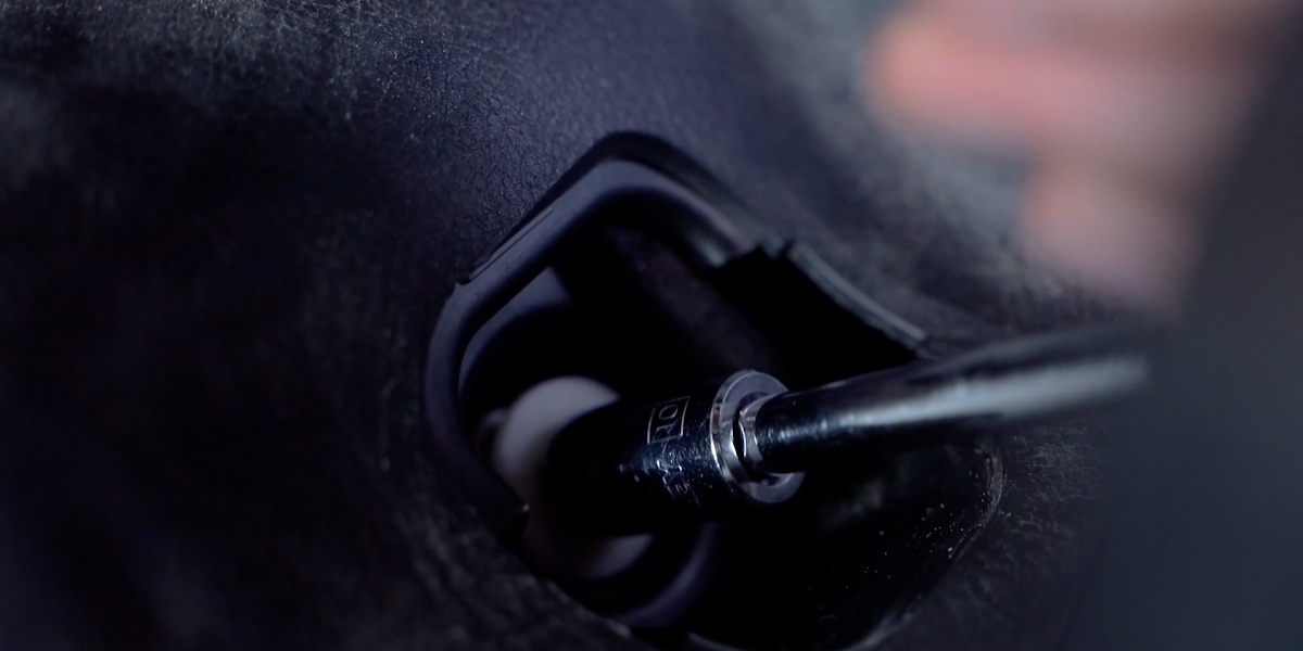
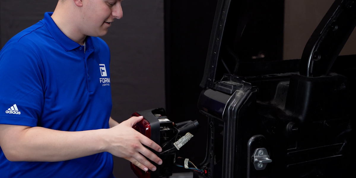
Open the tailgate and lift the rear window for access. Lift the black interior cover with a trim tool, then remove the retaining bolt with the 10 mm socket.
2. Remove and disconnect the lamp
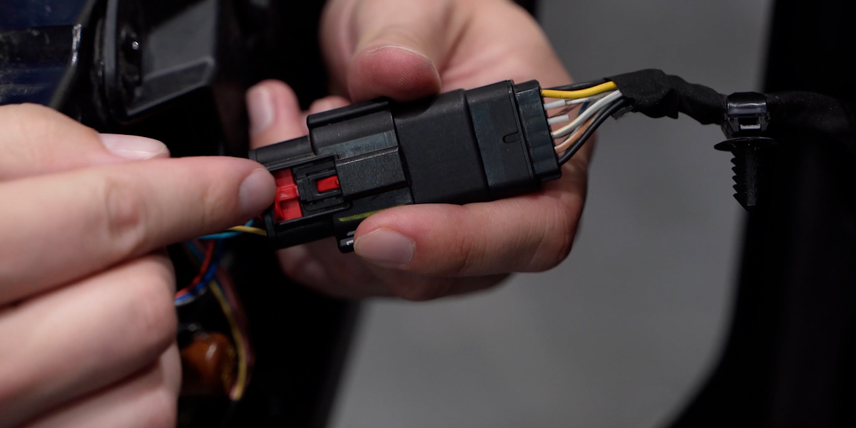
Support the lamp and pull it up and away from the vehicle as shown. Unlock the red tab and disconnect the original harness.
Transfer blind-spot modules
Complete this section only if the Jeep has factory blind-spot equipment. A vehicle without a module skips to the wiring and installation sections.
3. Open the original module compartment
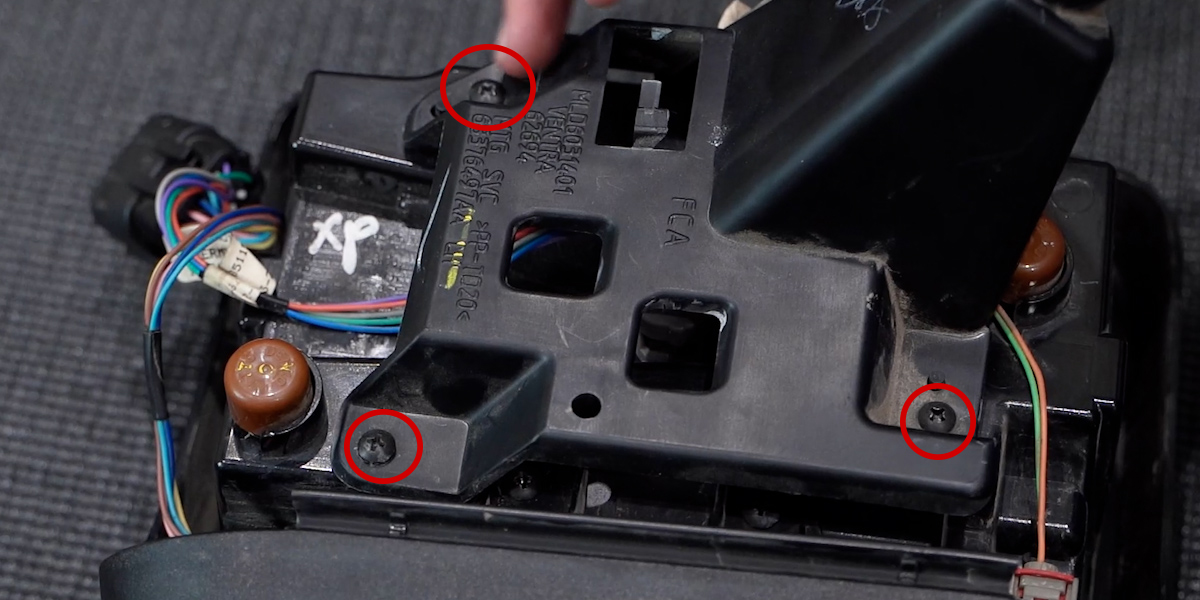
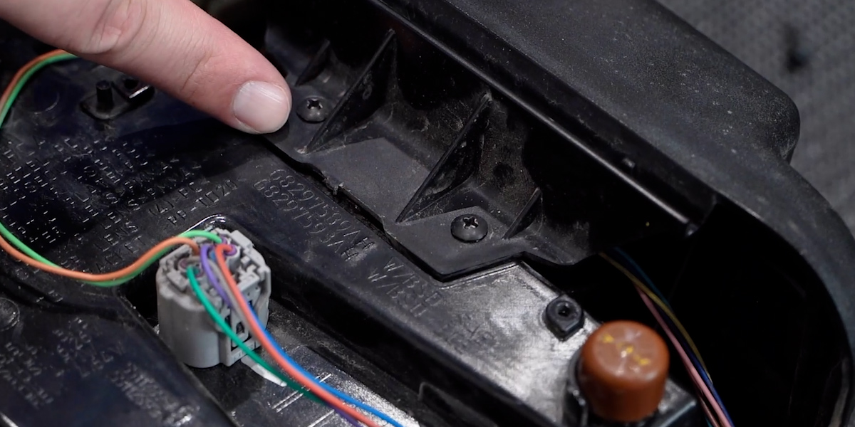
Remove the three Phillips screws from the rear trim bracket. Lift that trim away to expose two more Phillips screws, then remove those screws and the cover.
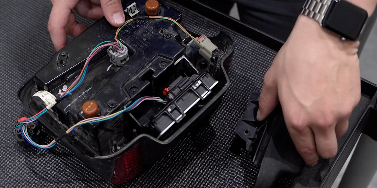
4. Transfer the original module
Release the carrier’s retaining tabs and remove the module. Slide down the red connector lock and unplug it. Install that same module in the new FORM housing by reversing the removal sequence, retaining its original side and orientation.
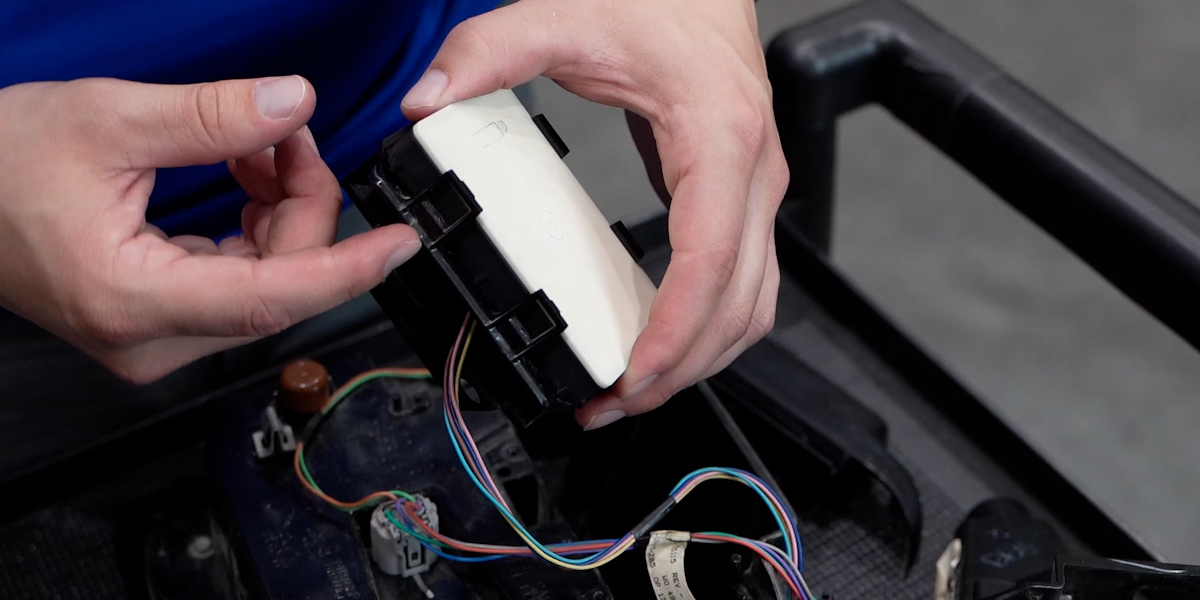
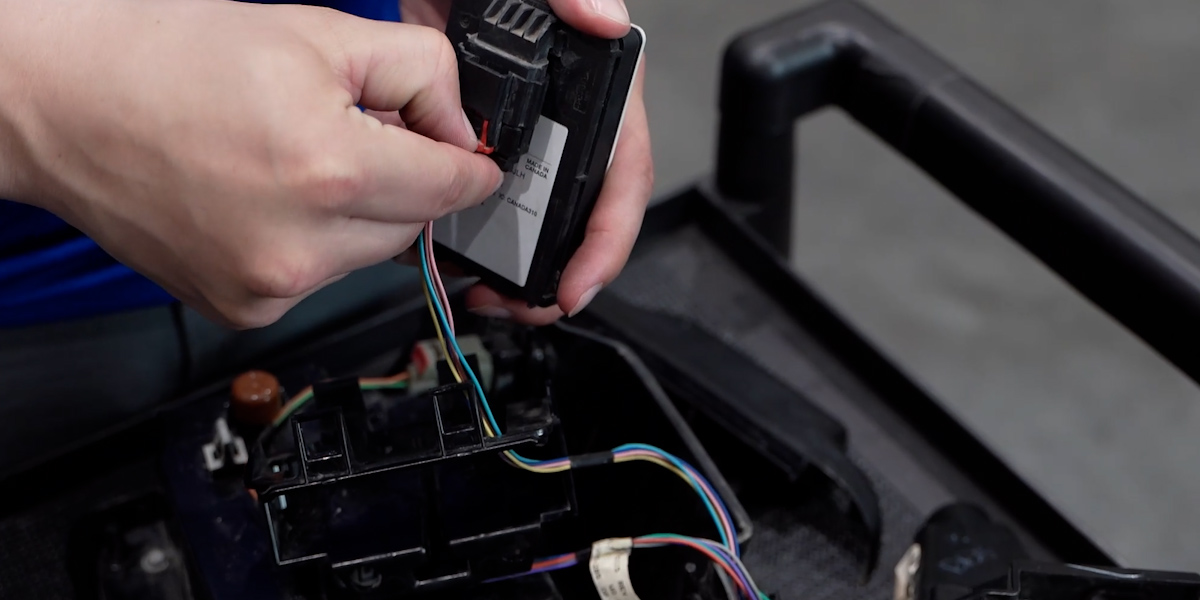
Optional sequential amber signal
This is the additional front-to-rear signal lead, not a replacement for the rear lamp’s main connector. Match the illustrated connector orientation before removing a cavity plug.
5. Identify the sealed connector cavity
Find the cavity marked in the manufacturer photograph, described in the article as the third pin over. Use the photograph’s connector orientation rather than counting from an arbitrary side. Remove the plastic pin separator with needle-nose pliers.
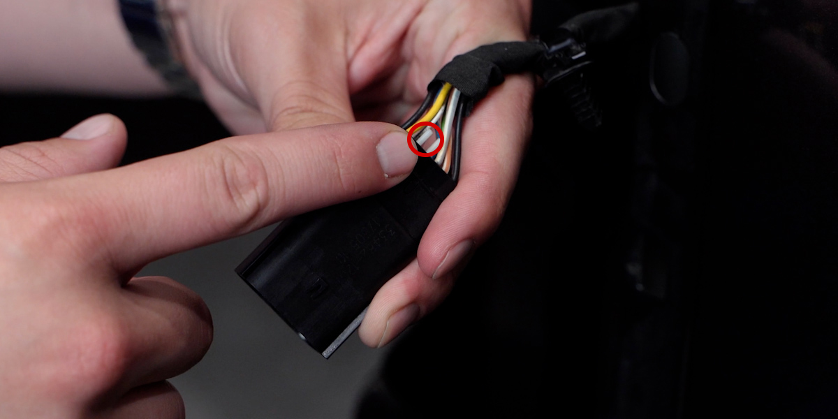
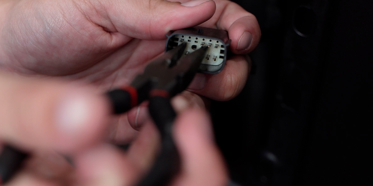
6. Release the cavity plug
Push gently from the back of the connector while using a pick to release the black retaining latch inside. With the latch released, use needle-nose pliers to pull out the cavity plug.
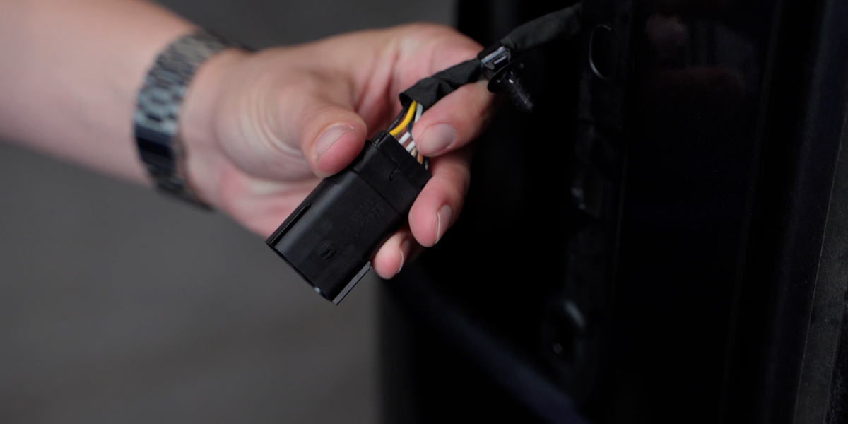
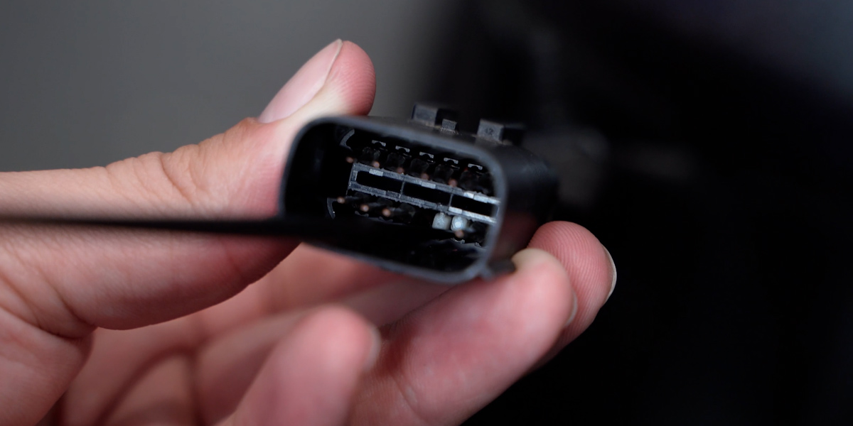
7. Insert the supplied terminal
Seat the supplied harness terminal in the opened cavity. Its closed side faces the middle of the connector. Reinstall the plastic pin separator after the terminal is fully seated.
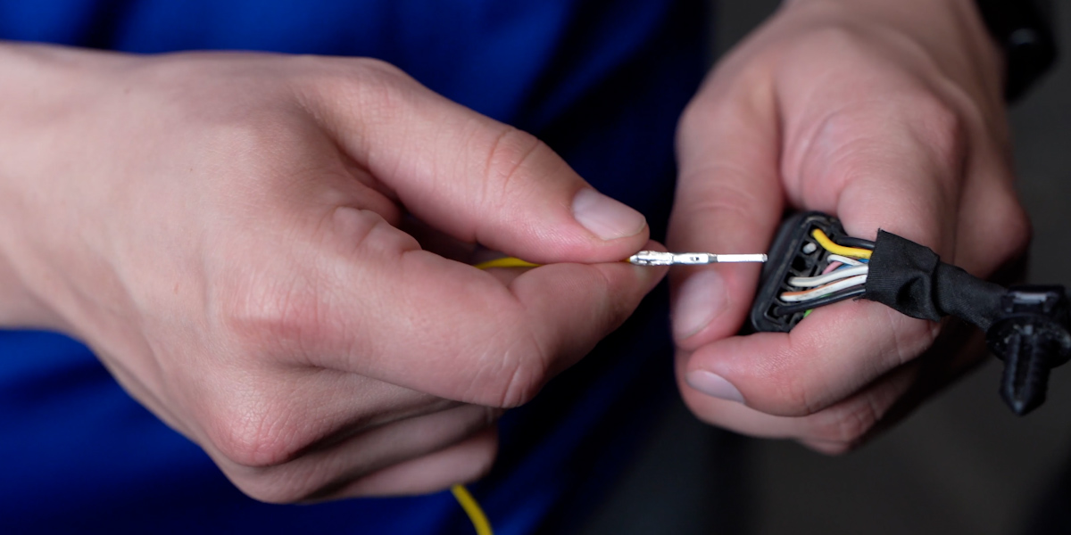
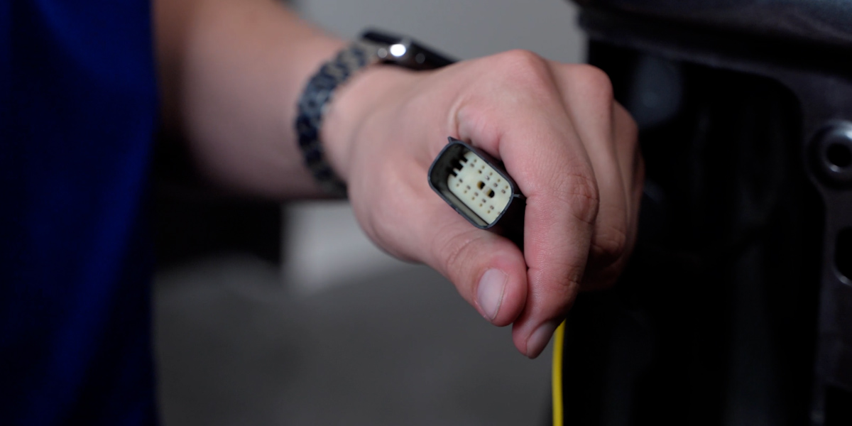
8. Route the lead forward
Feed the lead down through the empty tail-lamp opening. Route it under the vehicle toward the front fender alongside suitable factory wiring, keeping it clear of heat and moving parts and securing it with cable ties.
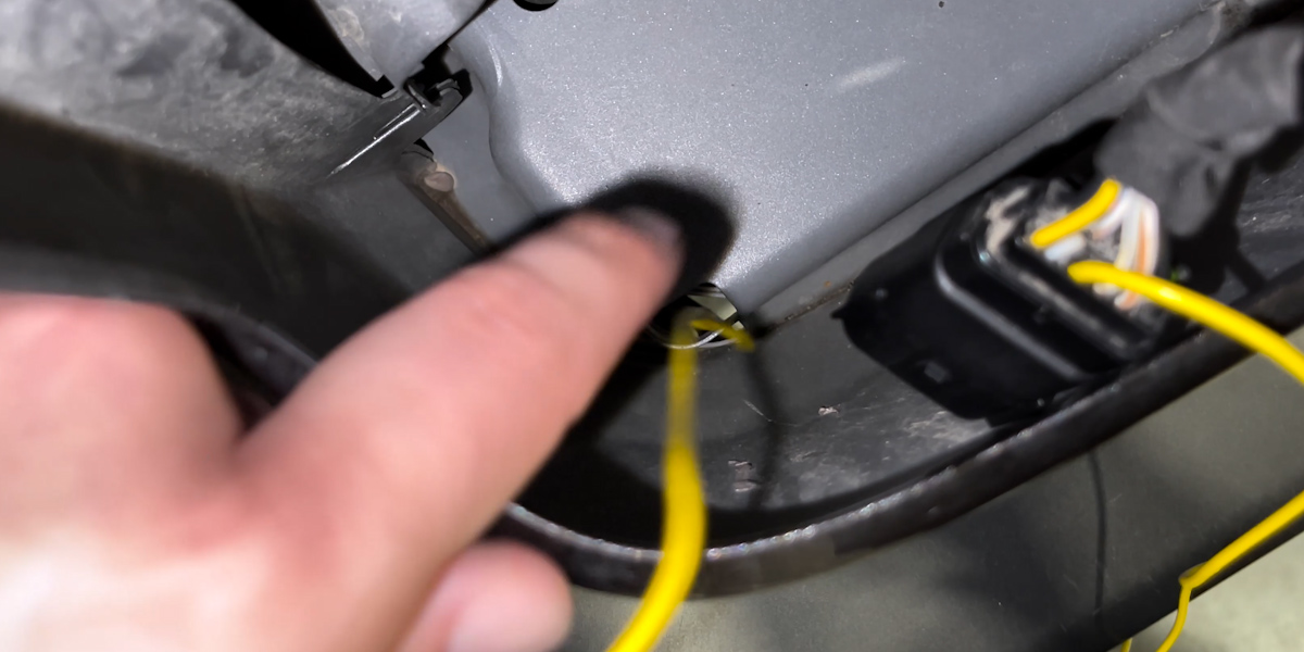
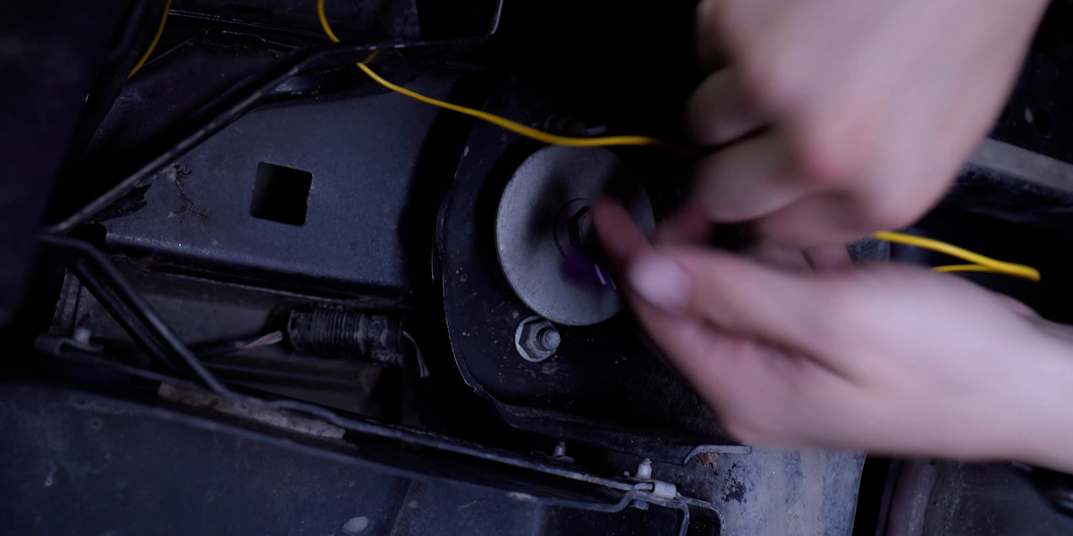
9. Access the front signal connector
At the front fender liner, remove the four plastic clips, two 8 mm screws and two 10 mm screws identified in the FORM procedure. Move the liner for access and bring the lead up beside the existing wiring.
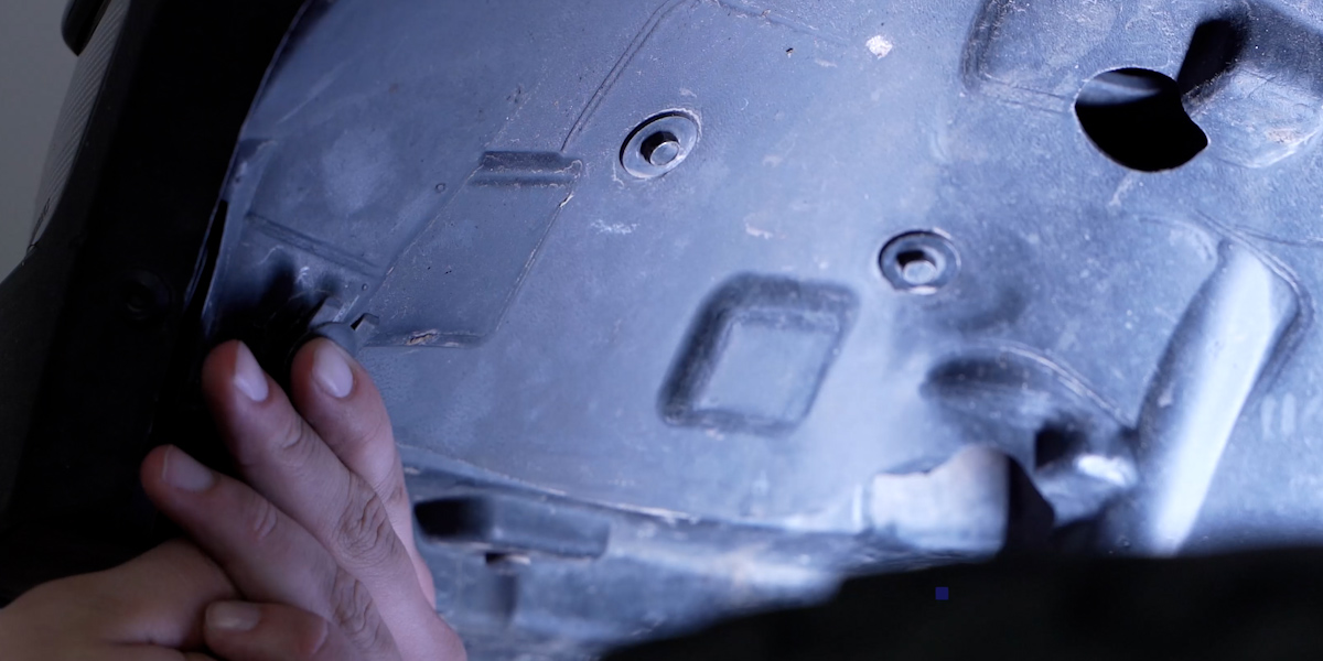
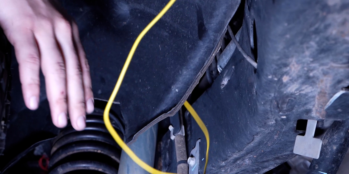
10. Make the signal tap
Identify the white-and-green wire at the rear of the DRL housing harness shown by FORM. Close the supplied T-tap fully around that wire, then connect the added harness to the tap. If the vehicle’s wire or connector arrangement differs from the illustration, confirm that circuit before making a connection.
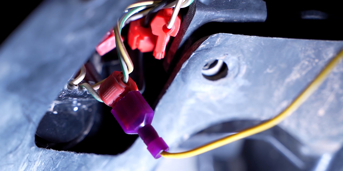
Refit and test
11. Connect and secure the new lamp
Connect the new tail lamp to the original rear connector and reinstall the 10 mm retaining bolt. Check the lamp functions before replacing the access cover and refitting the front liner. Repeat the complete process for the other side.
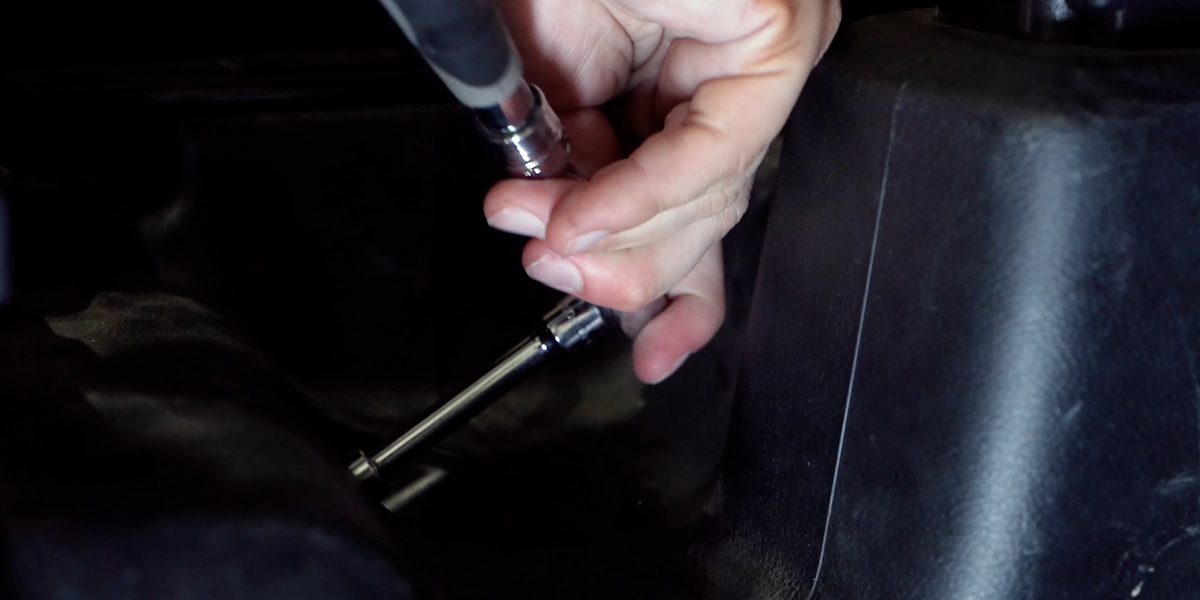
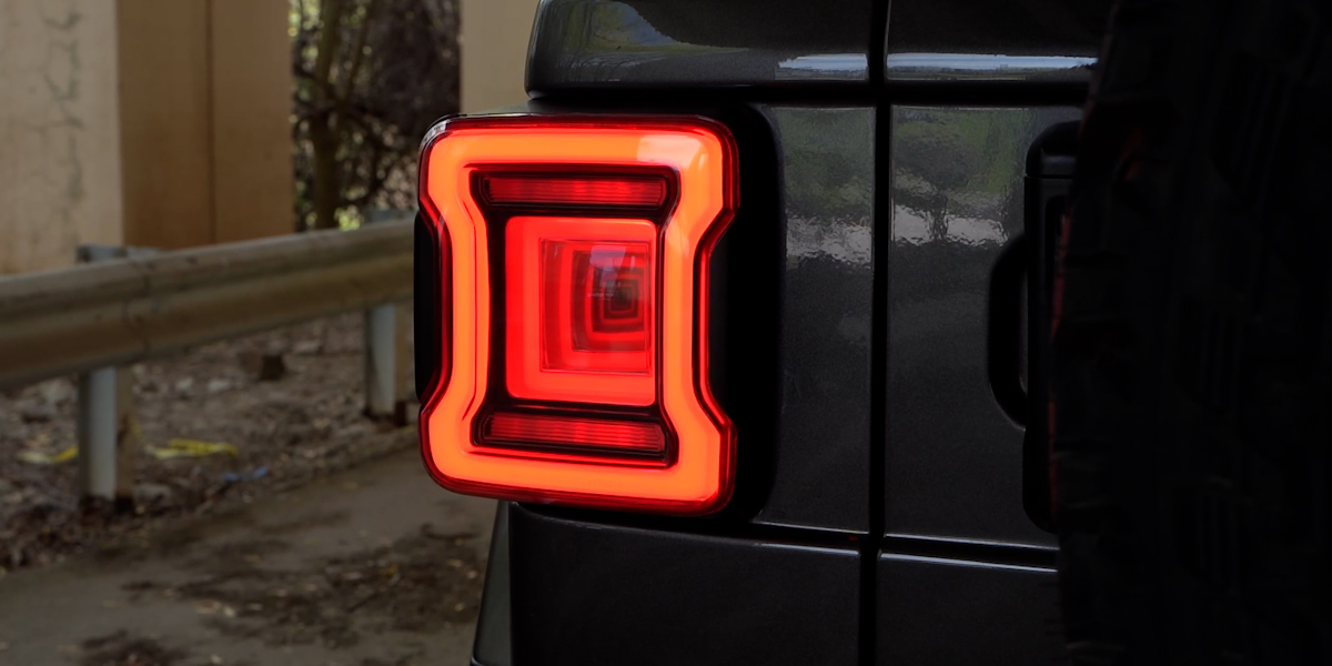
Watch the manufacturer video
Manufacturer video linked from the exact product or installation page. Follow the written equipment branch for your vehicle.
Instructions and matching products
Original technical photographs and diagrams: FORM Lighting. BTS explanatory text prepared from the linked instructions and current product information, checked October 24, 2026. No revision number is printed on the retained manual unless shown in the original file.