

BTS installation guide · Jeep lighting
Jeep JL Morimoto XB Fender Light Installation
Replace the 205 mm fender DRLs and follow the correct factory LED or incandescent wiring branch.
This procedure is for LF513.2 on Wrangler JL with the 205 mm factory DRL assembly. Sport, Willys Sport and Willys configurations listed as excluded by Morimoto do not use this fitment. Compare the actual lamp and connectors before beginning.
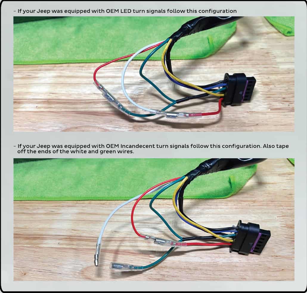
Vehicles with OE LED DRLs require a Pin 4 side-marker connection. Confirm the correct connector cavity for the supplied harness before making that tap; the original connector photographs below do not number that pin, so do not choose it from wire colour alone.
Tools: ratchet and 10 mm socket, T30 bit, 7 mm wrench, trim tool or flat screwdriver, #2 Phillips screwdriver, scissors and a heat gun.
Parts and lamp choice
1. Lay out the assemblies and harness parts
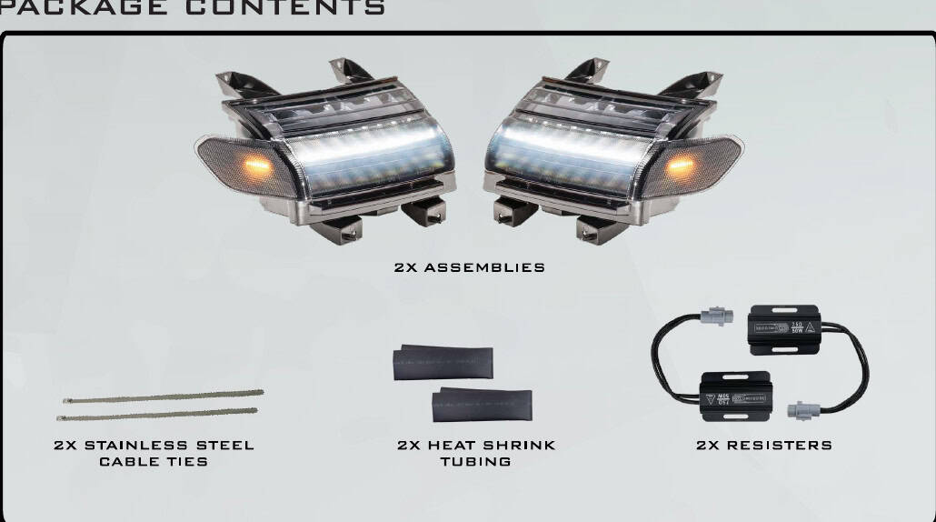
The manual shows a pair of DRL/turn-signal assemblies, two stainless cable ties, two lengths of heat-shrink tubing and two resistors. Keep the original amber side markers if using the manufacturer’s stated compliant configuration; the optional smoked markers are not DOT compliant.
Remove the fender
2. Release the liner fasteners
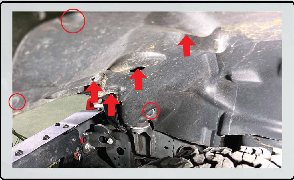
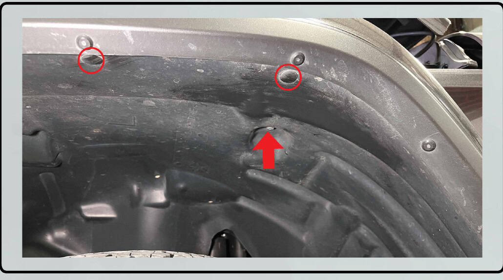
Start on the driver side. Remove the three push clips and four 10 mm bolts shown, then the rear 10 mm bolt and two remaining push clips.
3. Unplug the fender harness
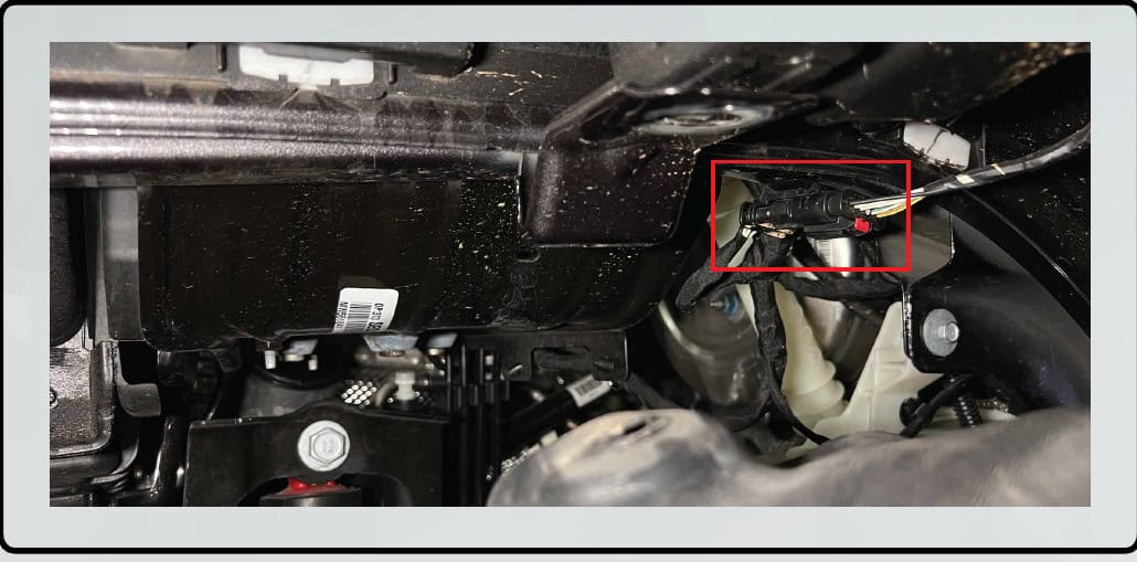
Lower the liner, find the middle connector, slide the red lock back and press the release to separate it.
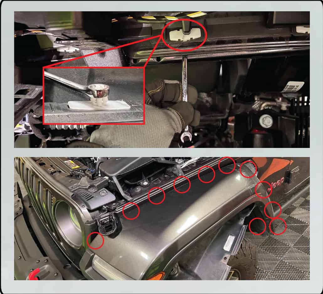
4. Release all eleven fender clips
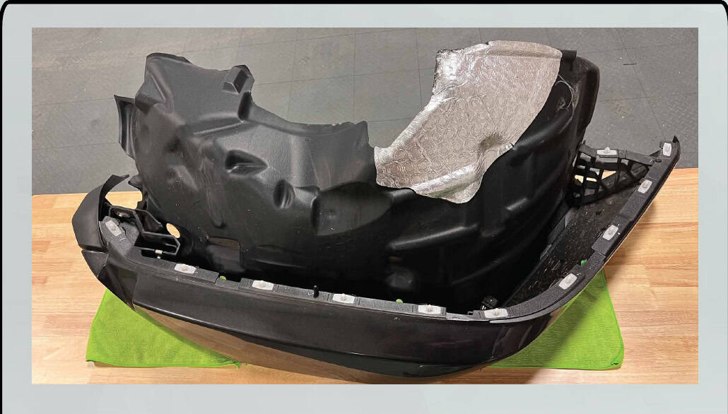
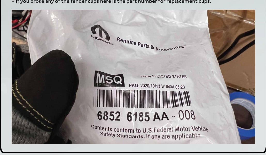
Fit the 7 mm wrench over each clip head to compress it, then release it from the body. Hold the freed part of the fender away so the clip cannot latch again. Support the fender and place it on a soft surface. Replace damaged clips before reassembly.
Replace the light assemblies
5. Open the underside of the fender
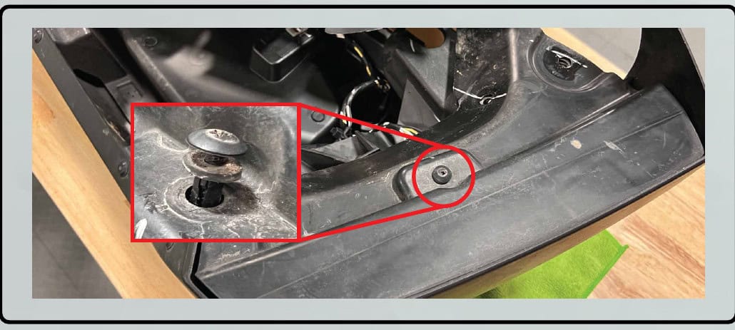
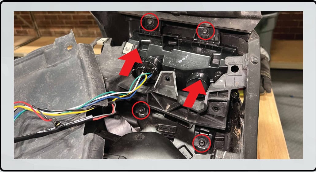
Unscrew the head of the Phillips push clip under the signal and lift the clip body out. Raise the flap and remove the eight T30 screws. Keep track of their positions because the fasteners are not all identical.
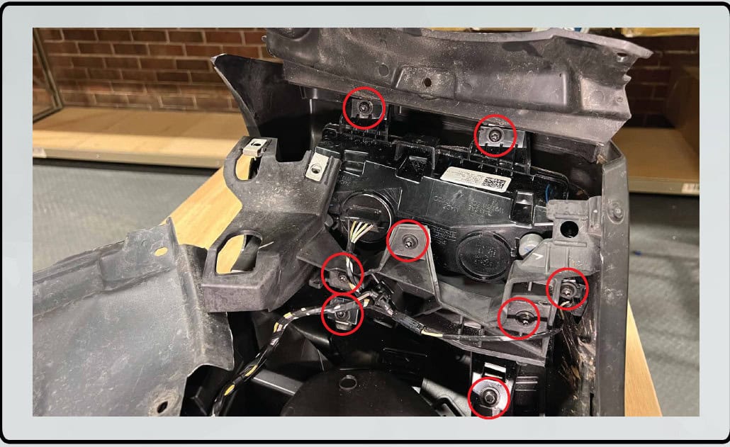
6. Remove the original marker and DRL
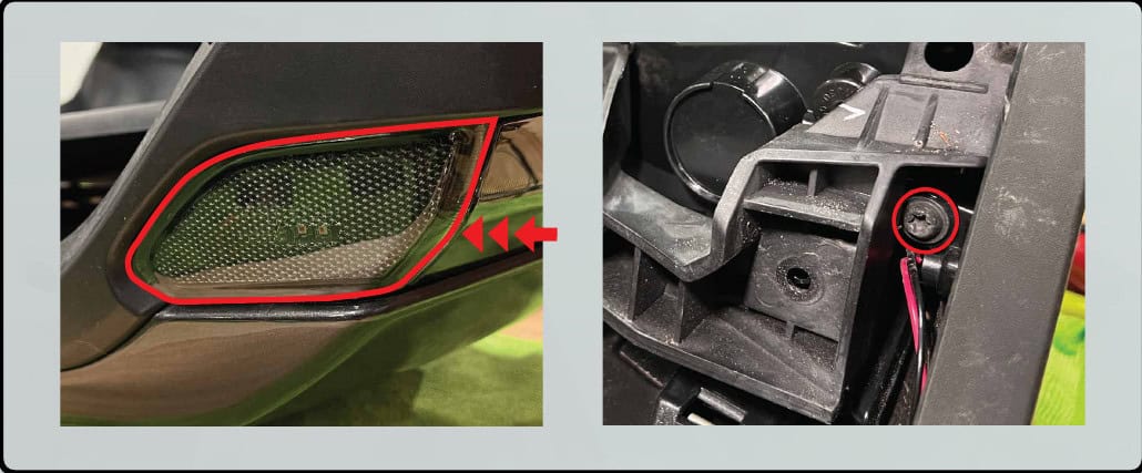
Release the wiring clips and unplug the side marker. Slide the marker out. Rotate the bracket up and away, then move the turn-signal housing back; its adhesive strip also has to release.
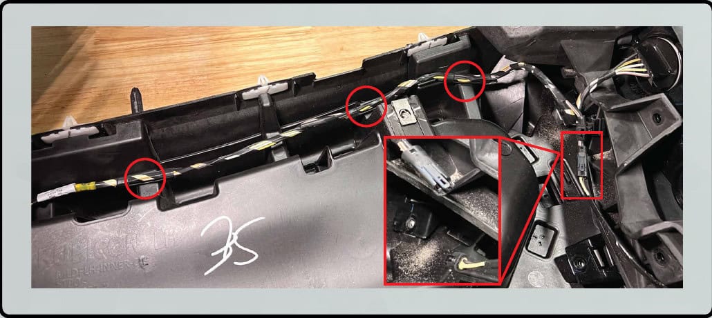
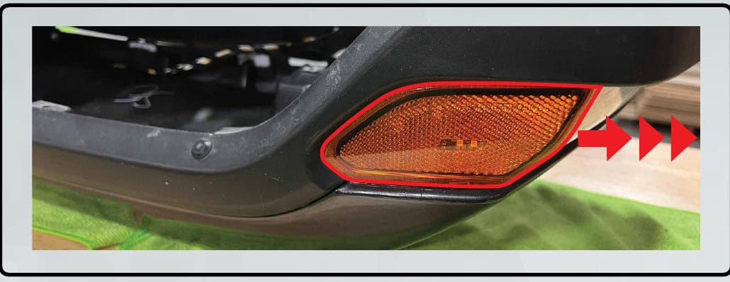
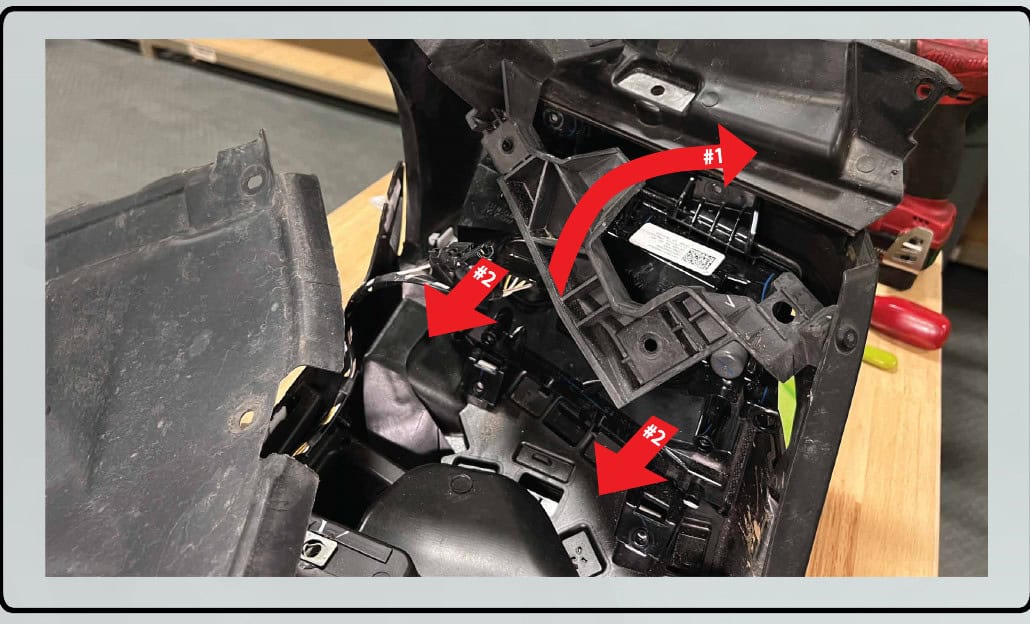
7. Seat and fasten the new lights
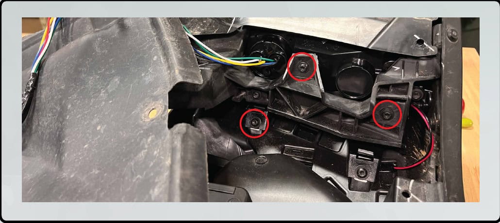
Slide the new turn-signal housing into position and start its four screws loosely. Slide the selected side marker in from the front until its clips seat, then fit its rear fastener by hand. Install the remaining three bracket screws and tighten those plus the four started screws by hand.
Wire, protect and refit
8. Mount the resistor and route the harness
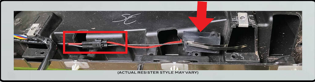
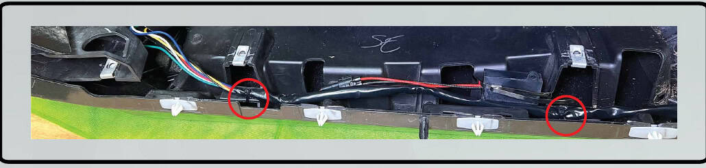
Connect the supplied resistor as specified for the harness, secure it using the included metal strap and route the wiring along the fender, using cable ties to retain it.
9. Protect the connector wiring
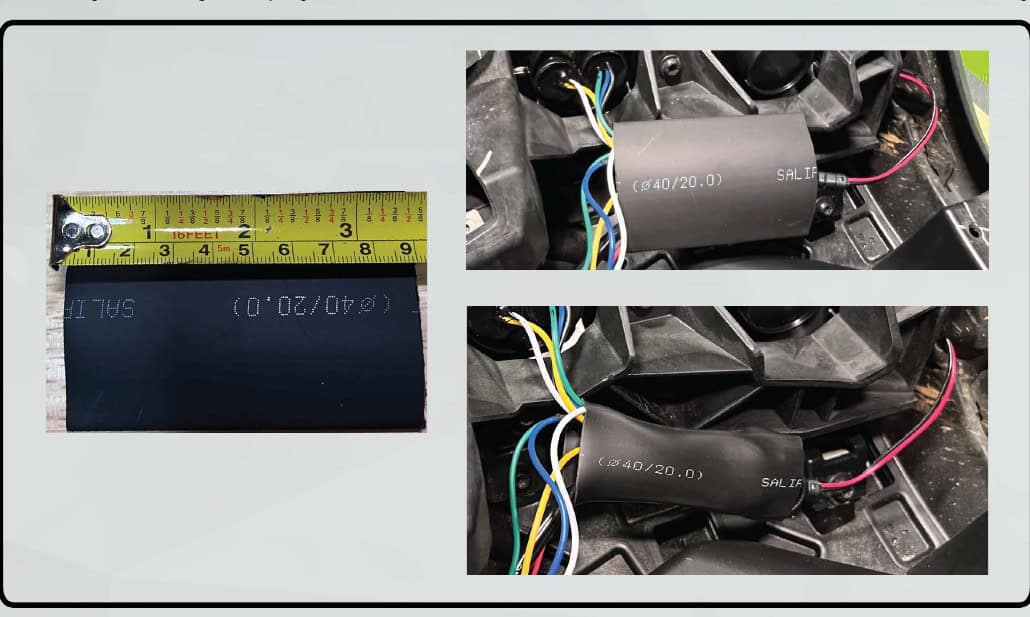
Cut a 3.5-inch length of the supplied heat shrink. Place it over the excess wiring at the rear of the housing before joining the side-marker connector, then shrink it with a heat gun as shown.
10. Confirm the factory-equipment branch
The upper original photo shows the OEM LED turn-signal configuration; the lower photo shows OEM incandescent. In the incandescent branch, the unused white and green ends are individually insulated. For OE LED DRLs, also resolve the current manufacturer’s Pin 4 side-marker requirement before final connection; the unnumbered photo cannot establish that cavity on its own.
11. Refit and check both sides
Refit the fender and reconnect the vehicle harness. Repeat the work on the opposite side. Check DRLs, both turn signals and side markers before closing up both liners.
Watch the manufacturer video
Manufacturer video linked from the exact product or installation page. Follow the written equipment branch for your vehicle.
Instructions and matching products
Open the original Morimoto PDF (11 pages)
Original technical photographs and diagrams: Morimoto. BTS explanatory text prepared from the linked instructions and current product information, checked October 24, 2026. No revision number is printed on the retained manual unless shown in the original file.