
Morimoto tail-light installation: 2010–2024 Toyota 4Runner
For Morimoto LF738 Red and LF739 Smoked tail-light pairs. The standard lamp swap and the optional BoostBar procedure are separate below. The BoostBar is sold separately.
Before you start
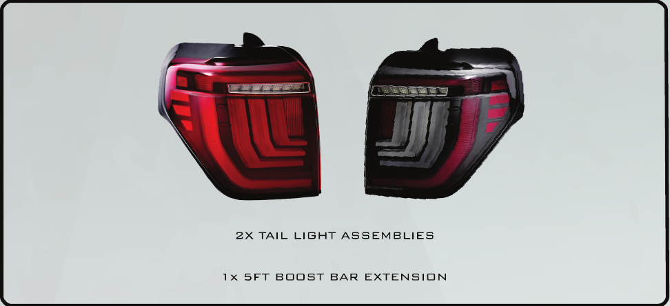
Use a panel pry tool and a 10 mm socket or wrench with an extension. Do not use power tools to tighten the lamps. The manufacturer lists two tail-light assemblies and a five-foot BoostBar extension in the tail-light package.
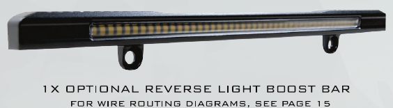
The optional BoostBar installation also needs cable ties and snips, electrical tape, and a drill/bit or file for the small wire clearance notch.
Standard tail-light swap
1. Open the access panels
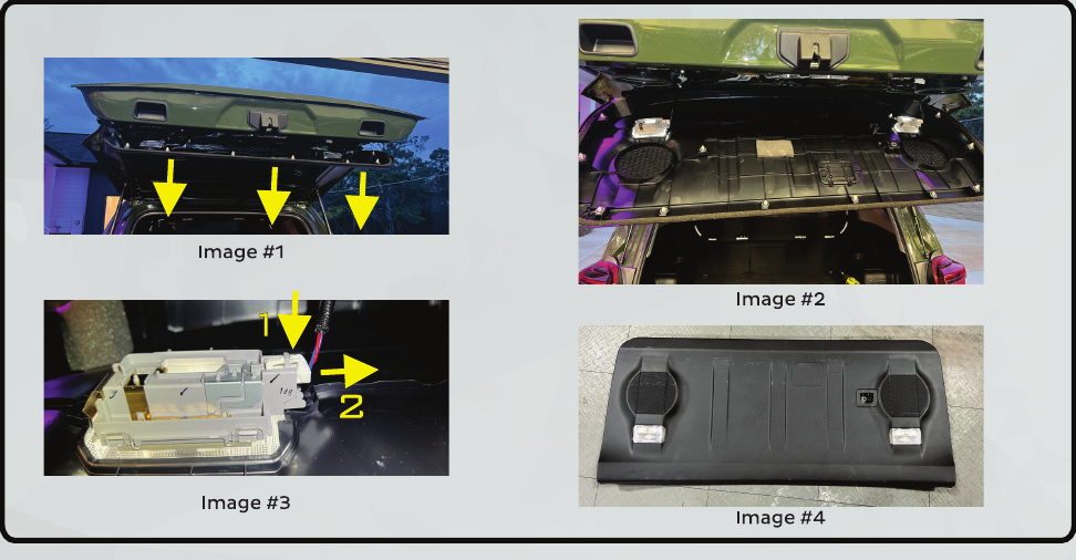
Fully raise the rear window, open the hatch and remove both interior access panels with a trim tool. Remove the two 10 mm nuts retaining each tail light.
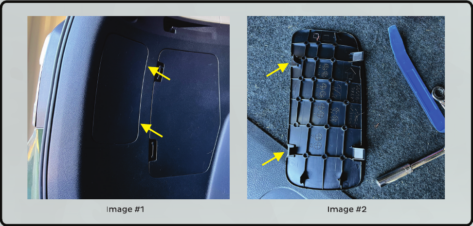
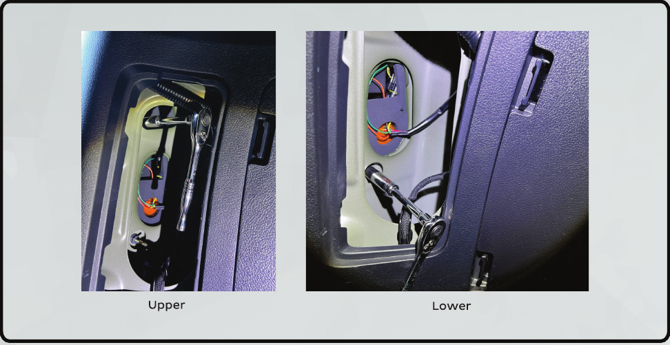
2. Release and connect the lamp
Pull the original lamp straight back and disconnect the circled factory connector. Connect the new lamp to that factory connection. If adding a BoostBar, complete the optional section before final reassembly.
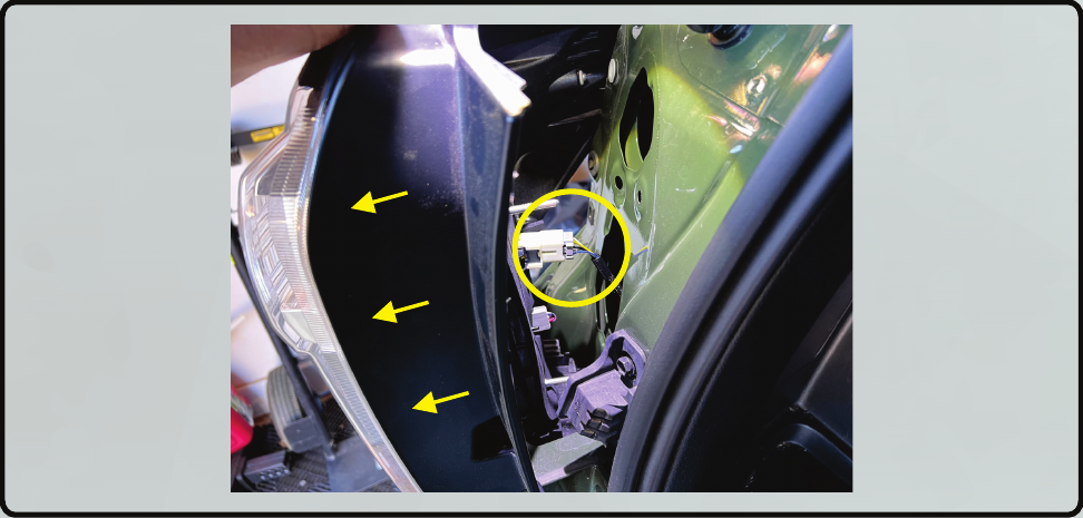
3. Align, test and secure
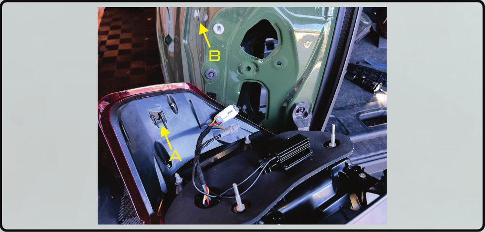
Make sure slot A locates into plastic clip B. Check every lighting mode, then reinstall the 10 mm nuts by hand until snug. Do not use power tools. Refit the access panels.
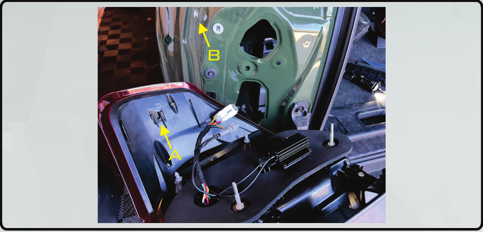
Optional BoostBar: open the hatch trim
Use this section only for a separately purchased BoostBar. Keep the rear window fully raised and keep the wiring clear of its travel.
1. Remove the inner hatch cover
Remove the cover above the cloth grab handle, then the 10 mm bolt and handle. Release the hatch trim nearest the latch first, work toward the closed window and slide the cover toward the front of the vehicle to release the window channel. Disconnect the two cargo-light plugs.
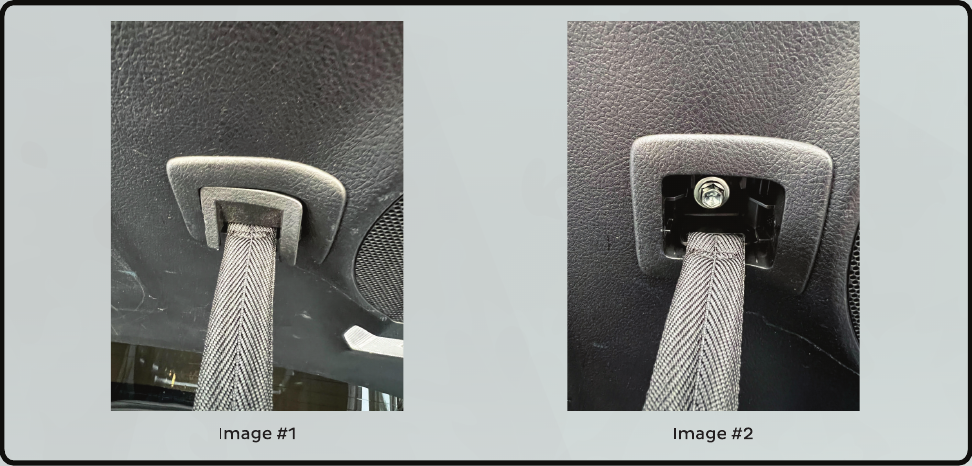
2. Expose the inner hatch
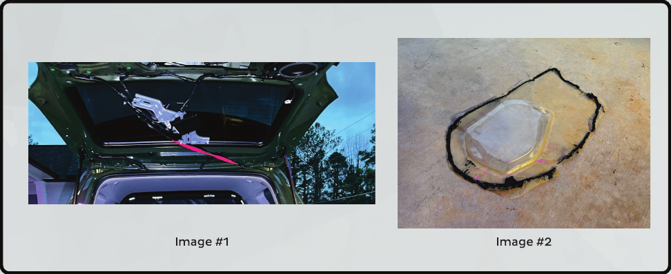
Remove the eight 10 mm screws and release the four push clips holding the centre frame and left speaker. Support the loosened bracket assembly. Carefully peel the vapour barrier from the butyl edge and set it sticky-side up for reuse.
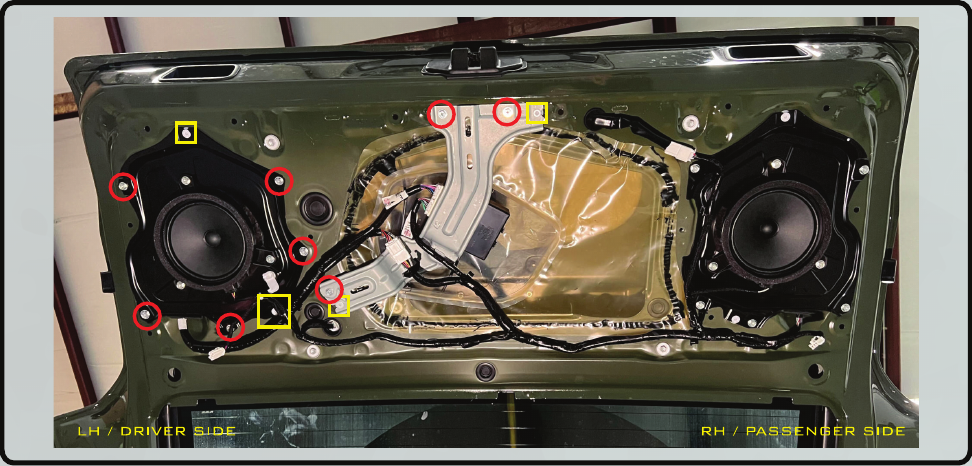
3. Release the outer handle
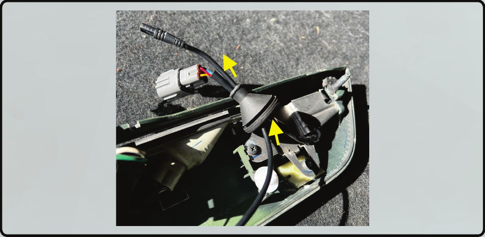
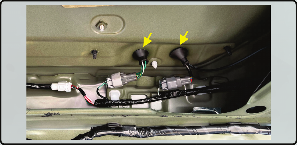
Remove the four 10 mm handle nuts. Two are accessed through the marked rubber-grommet openings with an extension. Unplug the three connectors and push the indicated grommets outward from inside the hatch.
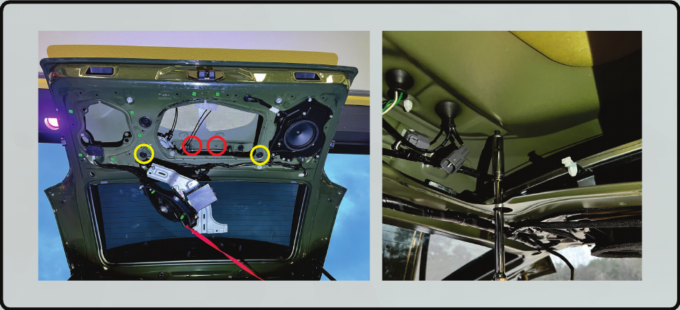
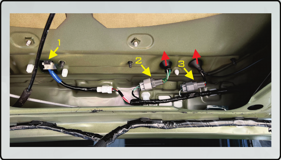
Lower the hatch slightly, but do not close it while the brackets are loose. Pull the centre handle away to release its press clips. Make the small wire-clearance notch with a drill or file as shown.
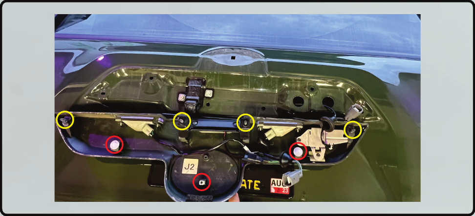
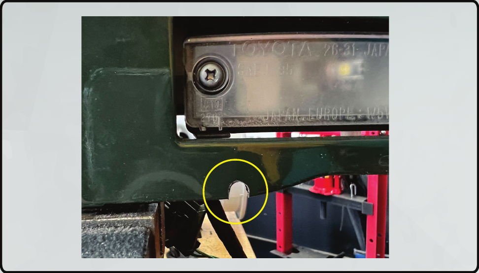
4. Mount the bar and reseat the handle
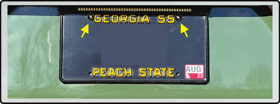
Remove the factory tape at the far-right window-switch grommet and route the BoostBar cable through it. Mount the bar above the licence plate using the existing screws. Reseat the rubber grommets, press the handle into place and reinstall its four nuts by hand.
Optional BoostBar: secure and route the cable
5. Keep the cable clear of the rear window
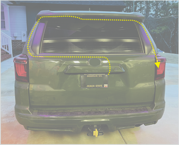
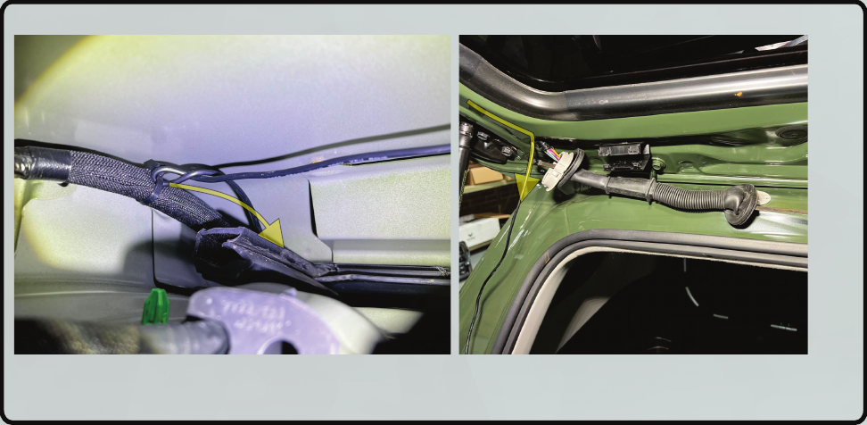
Route the wiring toward the left/driver side. Pull excess wire through the grommet and secure it at the marked connector and next stud. Keep it taut across the hatch so it cannot catch the opening or closing rear window. Secure it to the far-left factory loom and follow that loom upward.
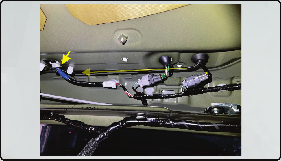
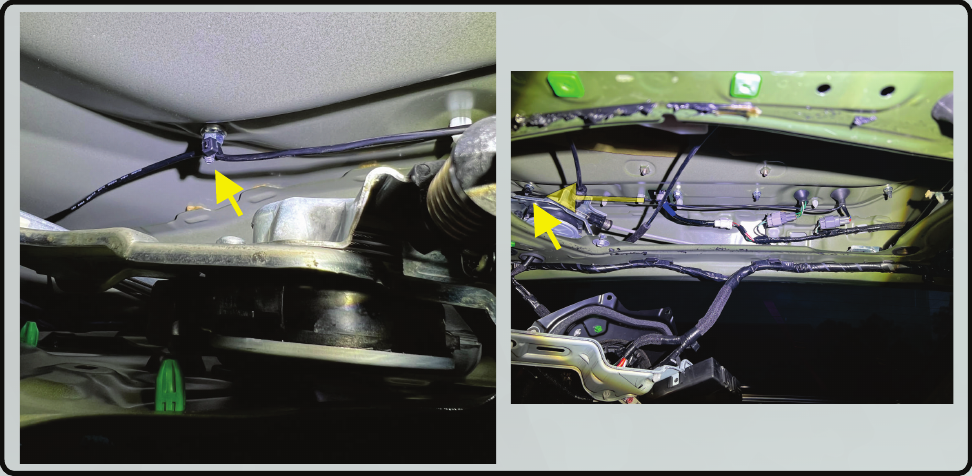
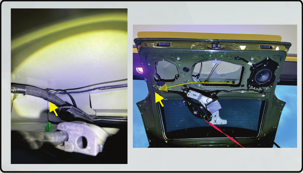
6. Pass through the factory boot
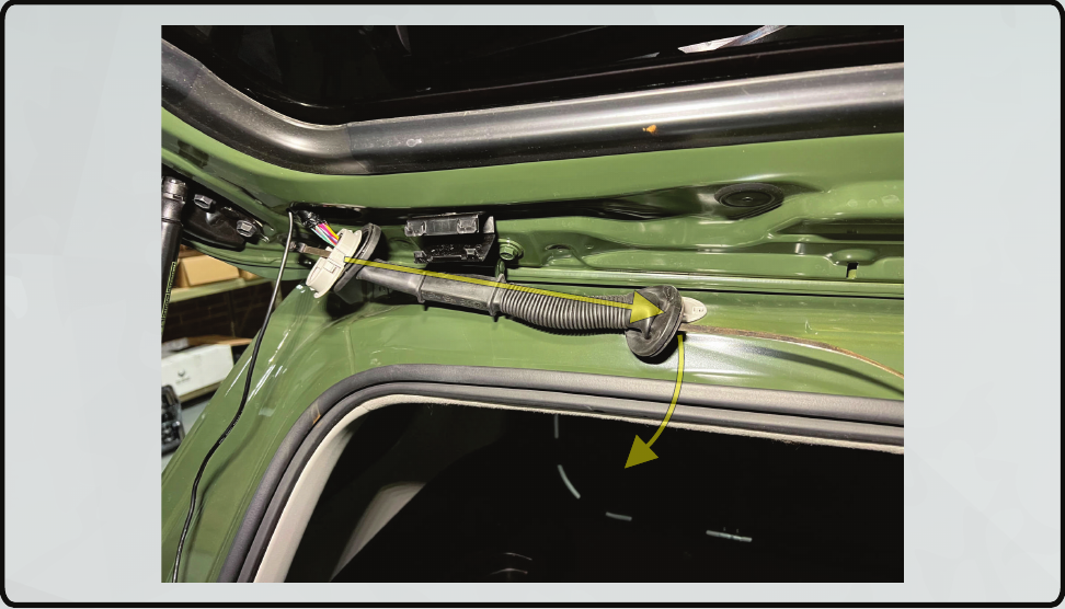
Release the two rubber boots between hatch and roof and open the support bracket. Remove the beige plastic inserts with a small trim tool or flat-blade screwdriver, and remove the old tape. When refitting, put each plastic insert inside its rubber boot and press the assembly into the sheet metal as one piece.
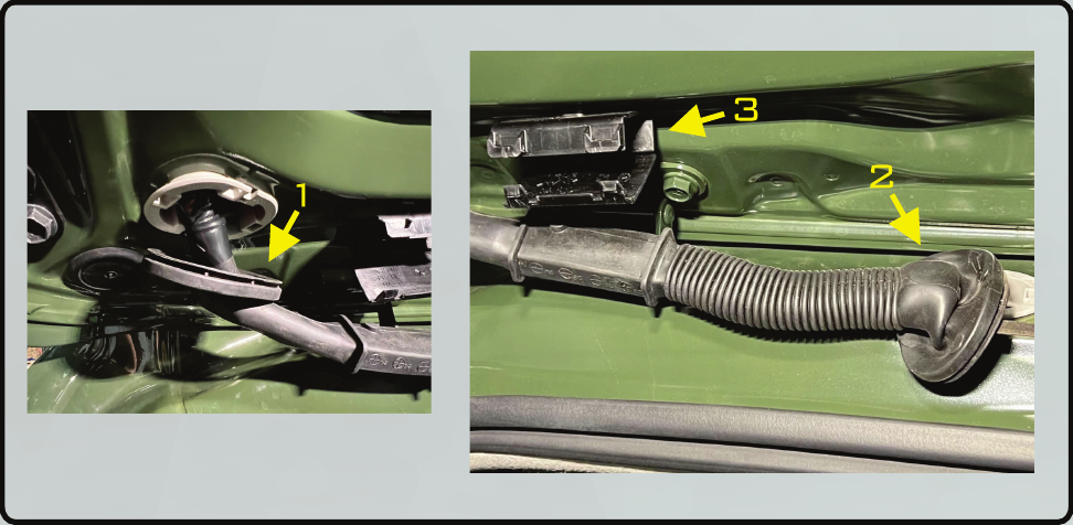
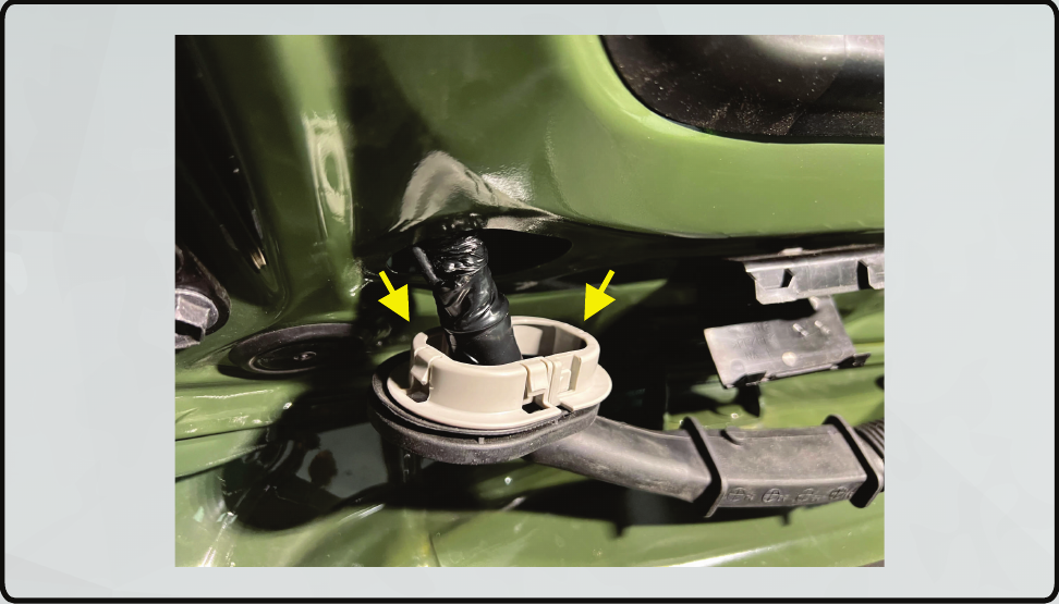
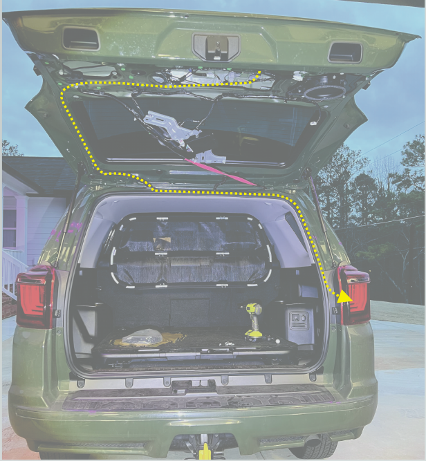
Feed the cable along the left side of the rear window, through the rubber boot and into the roof opening. Guide it out at the headliner edge; remove one or two plastic clips only as needed to lower that edge slightly.
7. Connect at the right tail light
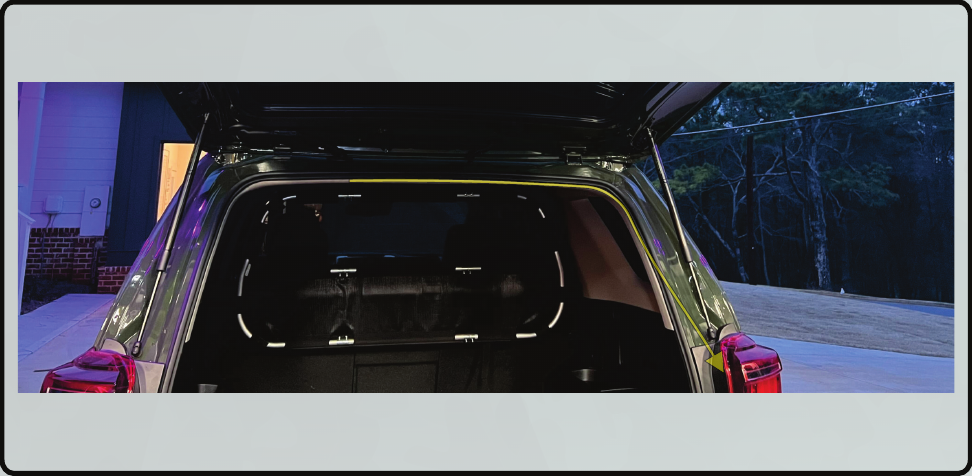
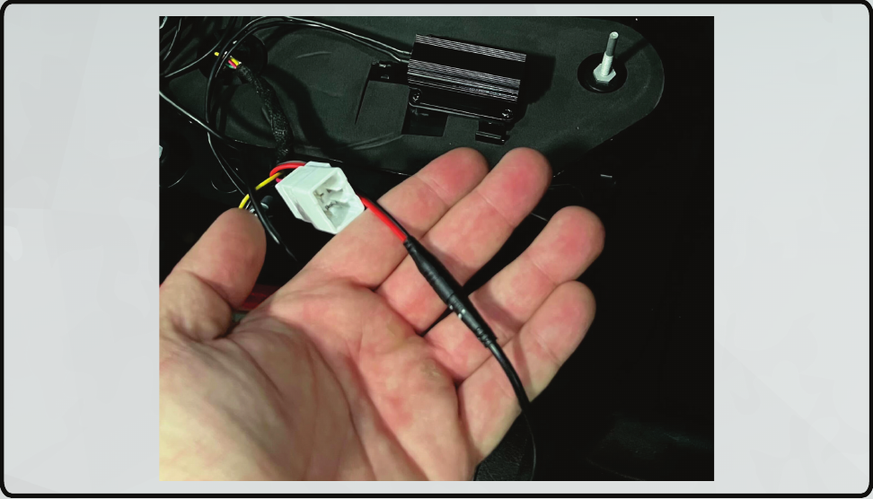
Add the extension to the BoostBar lead. Route it inside the headliner edge across to the right/passenger side and down to the tail light. Plug it into the tail-light connection shown.
Final lamp and hatch checks
Align slot A with clip B and install the tail lights. Check all lamp modes and the optional BoostBar. Confirm wiring stays clear of rear-window movement, then restore the vapour barrier, brackets, cargo-light connections and hatch trim removed for access. Tighten lamp nuts by hand until snug, without power tools, and refit the tail-light access panels.
Wiring-route reference
The manual’s final reference page is captioned 2010–2023; the complete installation guide is titled 2010–2024. Compare the actual hatch and routing points before using these diagrams.