

Add reverse lighting below the factory bumper
2021–2023 Ford F-150 · C1 / C2 2.0 reverse kits
This illustrated guide covers the vehicle brackets, pod mounting, tail-light access and wiring route for DD7374, DD7375, DD7376 and DD7377. Owners of DD7373P brackets can use the mounting steps, but must supply compatible lamps, pod brackets, hardware and wiring separately.
Not compatible with Tremor or Raptor. This installation uses connections at the vehicle lighting circuits. It is separate from a HitchMount kit and is not a plug-in trailer-socket installation.
Prepare the truck and parts
Plan for approximately 1–2 hours and work on a secure, stationary vehicle. Have a 13 mm socket and ratchet, 8 mm socket, 5/32-inch Allen key and 3/8-inch wrench ready. An in-cabin override switch also requires a 3/4-inch (19 mm) mounting hole and a suitable protected route through the firewall.
Check the exact wiring diagram and connectors supplied with your kit before making a connection. Keep power isolated while working on the electrical connections and follow the vehicle battery-service procedure.
Diode Dynamics demonstrates the 2021–2023 F-150 mounting and wiring route. The video may show an earlier pod housing; follow the supplied hardware for your selected C1 or C2 2.0 kit.
1. Fit the vehicle brackets and pods
Reuse the underside bumper bolts
Remove the indicated factory bolts with the 13 mm socket. Position each vehicle bracket and reinstall the original hardware in its original mounting location.
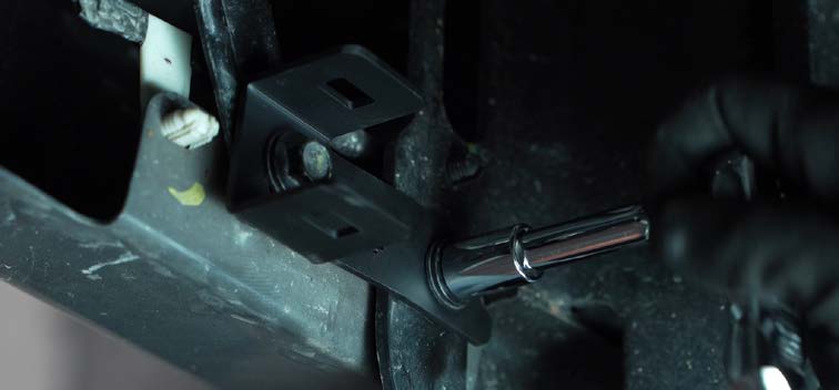
Attach the pod brackets
Use the supplied hardware to fasten a universal pod bracket to each vehicle bracket. Its curved portion faces the rear of the truck.
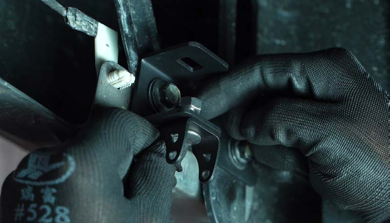
Install both lamps
Fit each pod using its supplied hardware. With the 5/32-inch Allen key and 3/8-inch wrench, tighten enough to hold the pod while leaving adjustment for final aiming. Repeat on the opposite side.
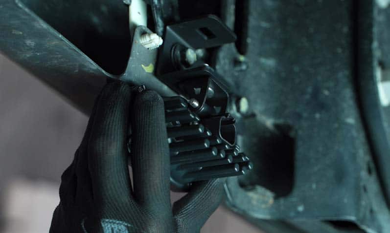
2. Access the tail-light wiring
Remove the retaining bolts
Lower the tailgate. Remove the two bolts beside the tail-light housing using the 8 mm socket.
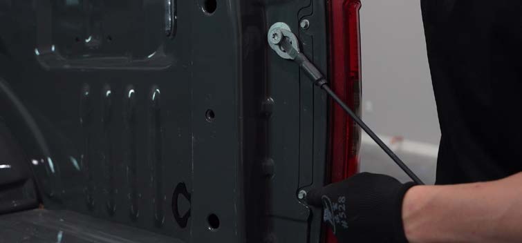
Release the housing
Support the housing at its top and bottom and pull it outward to release the locating retainers. Do not let it hang from the wiring.
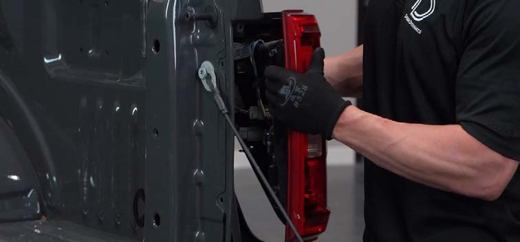
Unplug the connectors
Disconnect both connectors from the back of the lamp before routing the new harness alongside the vehicle wiring.
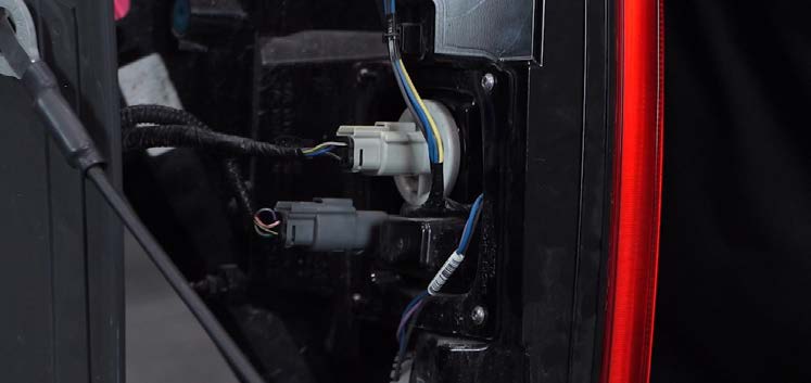
3. Route the harness and make the correct circuit connections
Battery power and relay
The harness uses a red ring terminal at battery positive and a black ring terminal at battery negative or the approved factory ground point. Secure the relay near the battery and keep the supplied fuse protection in place. Complete the remaining connections before restoring power.
Optional cabin override
Choose the switch location before routing. Unplug the switch from its harness to pass the wiring through a protected firewall route, then reconnect it. A flush-mounted cabin switch needs a 19 mm hole; check behind the panel before drilling. Protect the wiring from sharp edges and seal any penetration appropriately.
Run the loom to the rear
Route the connector end along the frame toward the rear bumper, away from exhaust heat, moving components and pinch points. Feed the signal leads up through the bed alongside the tail-light wiring. Secure the loom without stretching connectors.
Identify the reverse and parking-light circuits
Diode’s guide assigns the yellow main-beam control lead to the reverse-light circuit and the blue backlight control lead to the parking/running-light circuit, using the supplied T-taps. Connector layouts vary by equipment; the guide references 6-, 8-, 4- and 12-pin layouts.
Verify the actual circuit before tapping. The current illustrated guide does not publish a complete pin-number table for those layouts. Do not choose a wire by colour or connector size alone. Use the supplied kit diagram and the correct vehicle wiring information, or have a qualified installer confirm the circuits. Any alternate source must be properly fused.
4. Connect, aim and check operation
Plug the DT connectors into both pods. Set the aim for useful illumination behind the truck, then fully secure the lamp hardware with the 5/32-inch Allen key and 3/8-inch wrench. Reconnect the factory tail-light plugs, refit each housing and reinstall its original 8 mm retaining bolts.
- Check normal tail-light, brake, turn and reverse functions after reassembly.
- Confirm that the main white lamps follow the reverse-light signal and that the separate red accents follow the parking-light circuit.
- Check the override switch, then leave it in the appropriate normal-use position.
- Confirm the loom, fuse holder and relay are secure and clear of heat or moving parts.
The red backlight is an accent function, not an added brake or strobe mode. Use auxiliary rear lighting responsibly and follow local requirements.