

BTS INSTALLATION GUIDE
2014–2019 Toyota 4Runner SS30 stealth lightbar installation guide
2014–2019 Toyota 4Runner, excluding Limited and Nightshade. This lower-grille SS30 kit is not the 2020–2024 upper-grille SS6 kit.
Before you begin
10 mm socket, 14 mm wrench and a plastic trim tool or flat screwdriver; assistance for bumper removal.
Confirm that the kit, vehicle equipment and supplied instructions match before dismantling. Work with the vehicle safely parked and support any removed bodywork. Stop if connectors or mounting points differ from the shown application.
Watch the manufacturer installation
How to Install 2014-2019 5th Gen Toyota 4Runner Stealth Lightbar Kit | Diode Dynamics. Video loads only when selected.
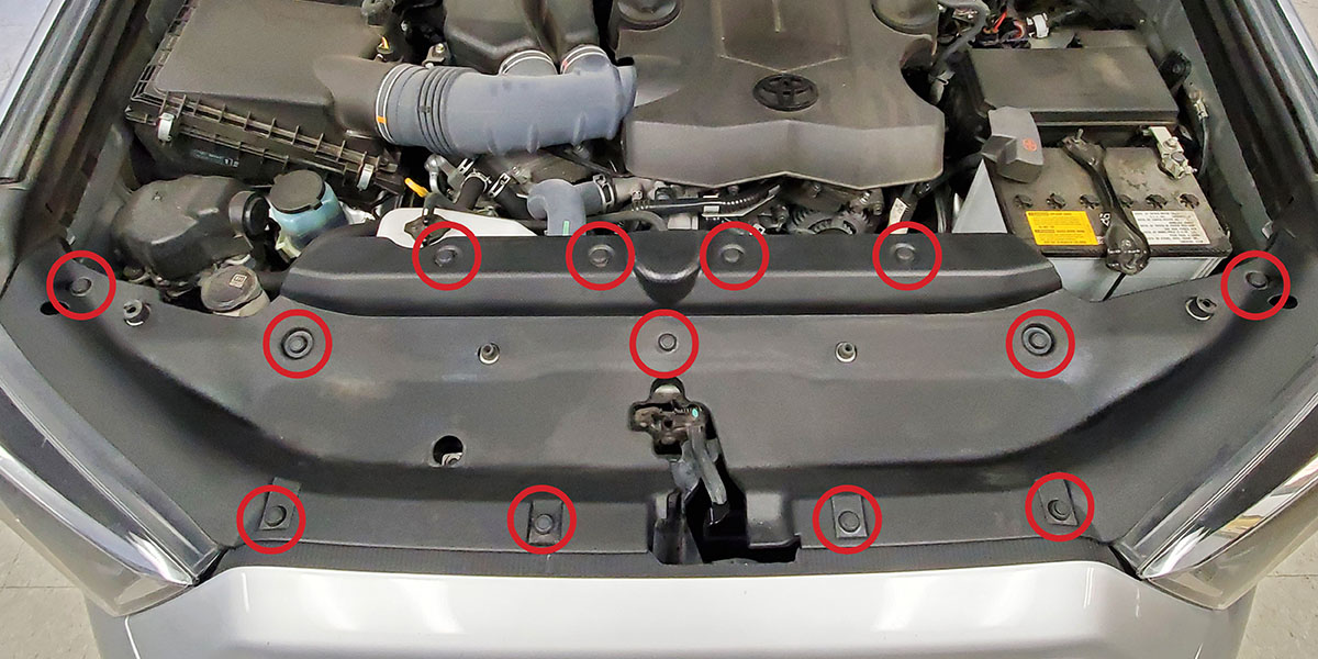
1. Remove the upper trim panel
Push the centres down and remove the thirteen push rivets holding the core-support trim. Reset each rivet by pushing its centre back through the top.
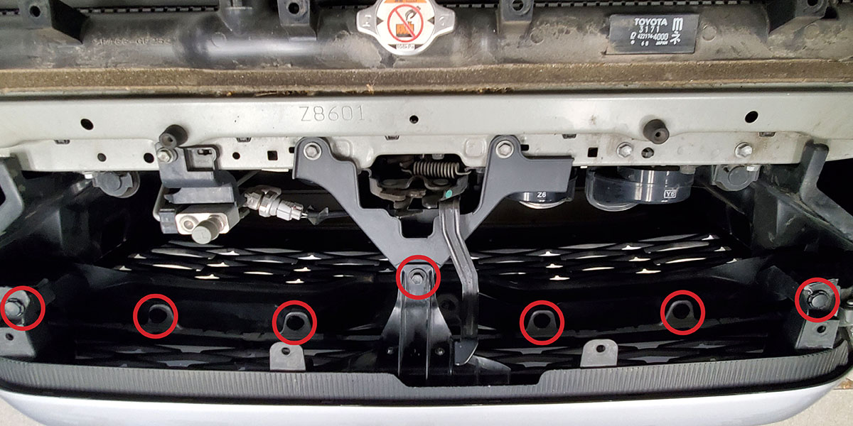
2. Release the top of the grille
Remove the six additional plastic push rivets shown. Remove the centre screw with a 10 mm socket.
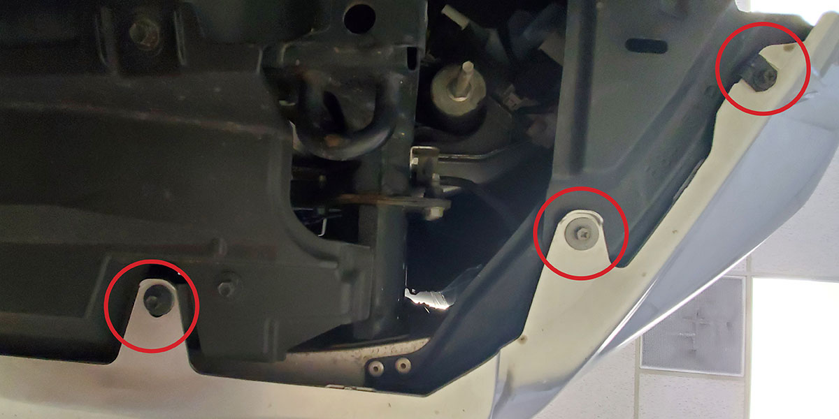
3. Disconnect the factory fog lamps
Remove the six screws across the underside of the bumper with a 10 mm socket. Reach underneath and disconnect the fog-lamp connectors.
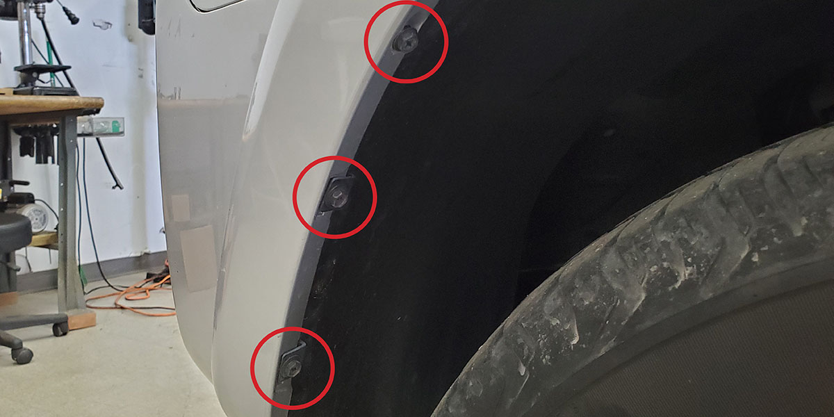
4. Remove the wheel-well screws
Remove the three screws securing the bumper edge inside each wheel well.
5. Release the bumper corners
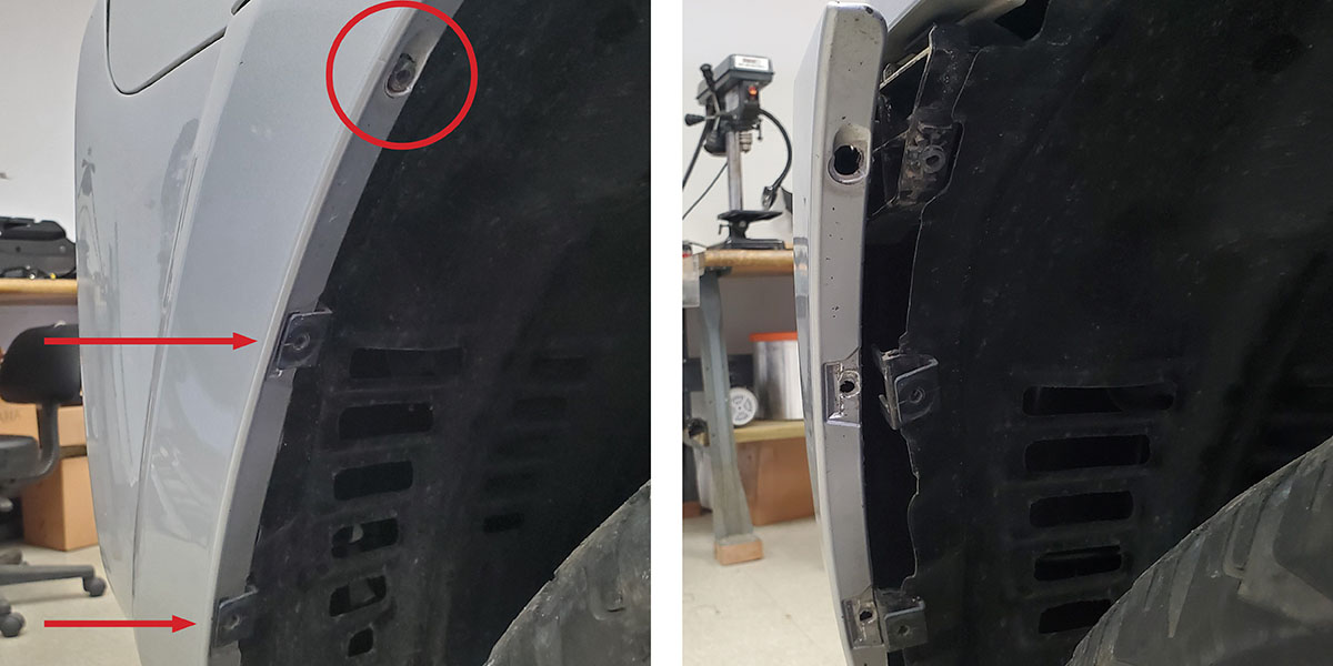
Use a trim tool to release the upper snap. Slide the lower screw clips off the bumper and carefully pull the corner away from the fender. Repeat on the other side.
6. Lift the bumper away
With a second person supporting it, pull the bumper straight forward to release the remaining snaps around the headlights. Set it down safely.
7. Release the air-dam rivets
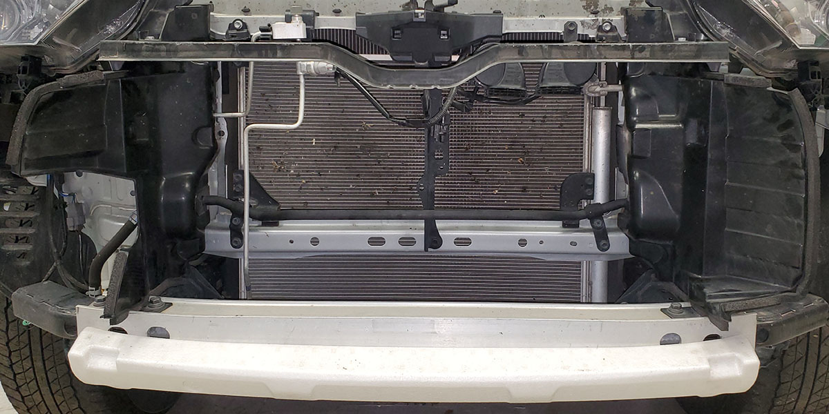
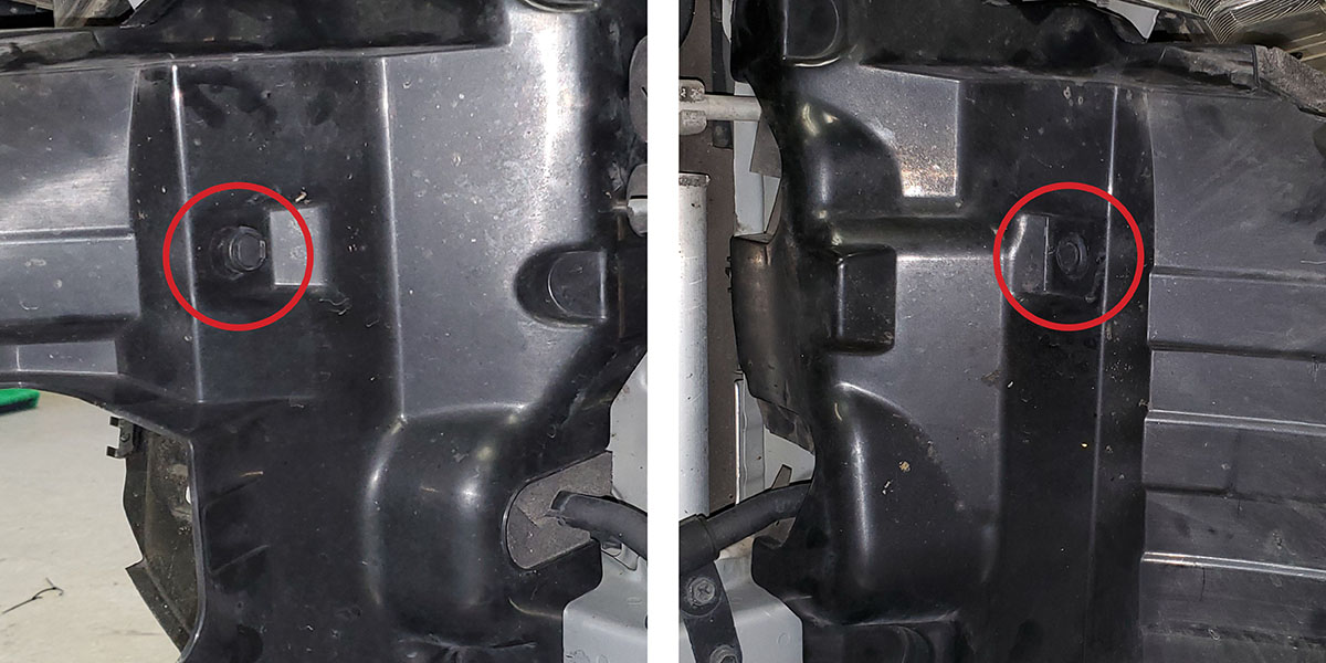
Remove the two plastic air-dam push rivets shown. Leave the air dams in place.
8. Loosen the bracket mounting bolt
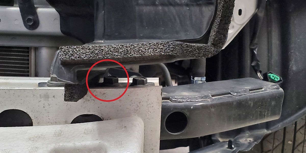
Use a 14 mm wrench to loosen the bumper-bar bolt identified in the photo: the second bolt in from the outer end.
9. Slide the brackets into position
Pass each bracket’s open slot beneath the air dam and under the loosened bolt.
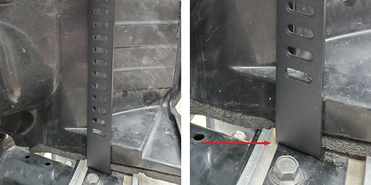
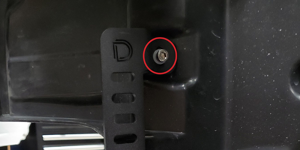
10. Loosely secure the air-dam mount
Fit the supplied M6 screw, washer and nut to the air-dam mounting point. Leave the adjustment loose for now.
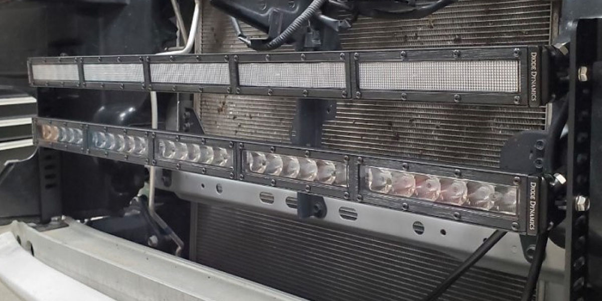
11. Install one or two bars
Use the supplied flanged M6 hardware to mount the SS30 bars. For two bars, the guide suggests the first and sixth, or first and seventh, slots from the top. Tighten the mounting hardware after aligning the assembly.
Wiring diagram
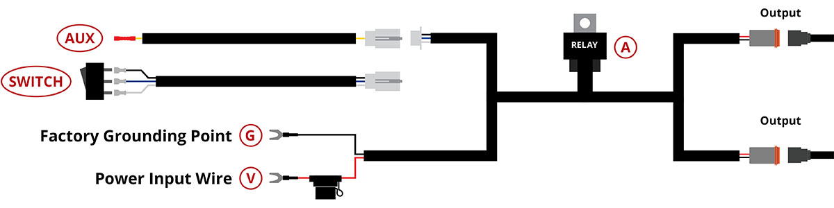
12. Locate the relay
Choose a secure relay mounting point near the battery or main power terminal. Use the fused harness supplied with the selected package.
13. Connect power and ground
Connect the red power lead to battery positive or the main positive terminal. Connect black to battery negative or a factory grounding point. All power sources must be fused.
14. Choose the switch arrangement
For a compatible auxiliary switch, unplug the switch lead at the white connector, insert the supplied pigtail and crimp its yellow wire to the auxiliary-switch lead. This lead controls the relay; lamp power comes from the battery. If no suitable switch bank is fitted, use the included toggle-switch adapter.
15. Connect the lightbars
Route the output wires clear of heat and moving parts, then connect them to the bars.
16. Check bumper clearance
Loosely refit the bumper before final assembly. If it touches a bar, move that bar farther rearward in the slots and recheck.
17. Reassemble and test
Reverse the bumper-removal sequence. Reconnect the factory lights and confirm the auxiliary lights operate as intended before use.
Choose or check your kit
Return to the product and its exact options. Explore Toyota 4Runner lighting
Plan your 4Runner lighting
Planning a 2014–2024 4Runner installation? Match the exact product and vehicle instructions before starting.
Shop 2014–2024 4Runner lighting · Read the 4Runner buying guide