

2014–2024 4Runner XB Evo & Evo Hybrid installation
BTS INSTALLATION GUIDE · LF2-531 / LF2-531Y
Identify your original headlight type, follow the correct fuse-feed route for your model year, then connect and aim the new lamps. This guide covers the shared installation and clearly separates Evo-only mode keys and heating from the nonheated Hybrid.
Match the factory lights first
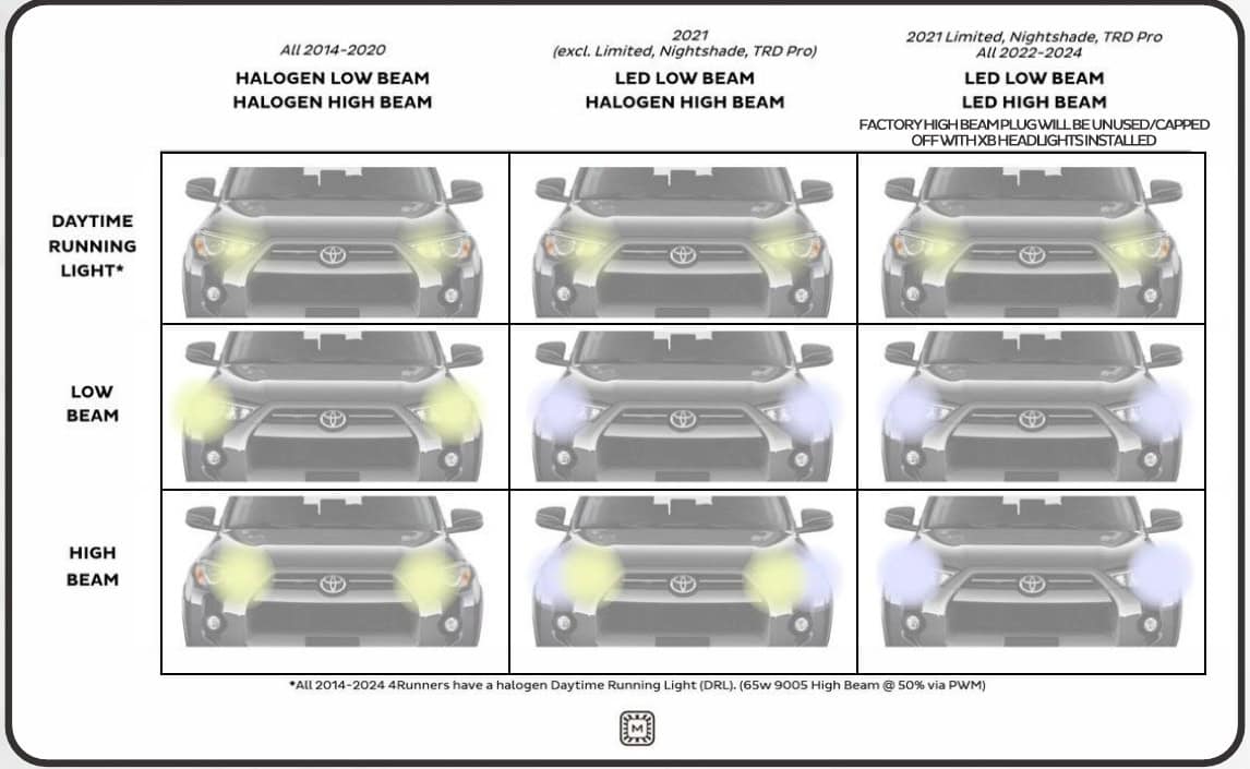
Check the original lamps and connectors before disassembly. The following branches come from Morimoto’s current 4Runner manual; modified vehicles need an equipment check rather than a model-year guess.
- 2014–2020
- Halogen low beam and halogen high beam: use the supplied halogen adapter.
- 2021, except Limited, Nightshade and TRD Pro
- LED low beam and halogen high beam: use the supplied LED adapter with its black connector cap removed.
- 2021 Limited, Nightshade and TRD Pro; all 2022–2024
- LED low and LED high beam: use the supplied LED adapter and cap the unused vehicle-side high-beam connector.
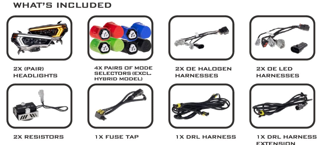
The Evo family includes its installation adapters. Separately listed LF531H and LF531H-2 harnesses are for the earlier XB headlight family; do not add them simply because your Evo installation uses an LED-equipment branch.
Tools and preparation
Have a ratchet and 10 mm socket, trim/pry tool, #2 Phillips screwdriver and zip ties ready. The 2014–2018 route also calls for a drill with a 7/32-inch bit or a small cutting tool. Work with the vehicle and lights off during connector changes; use a qualified installer if the wiring or removal procedure is unfamiliar.
Morimoto notes that other aftermarket exterior lights can affect turn-signal behaviour. Check all functions before putting the front end back together.
1. Release the grille and bumper access
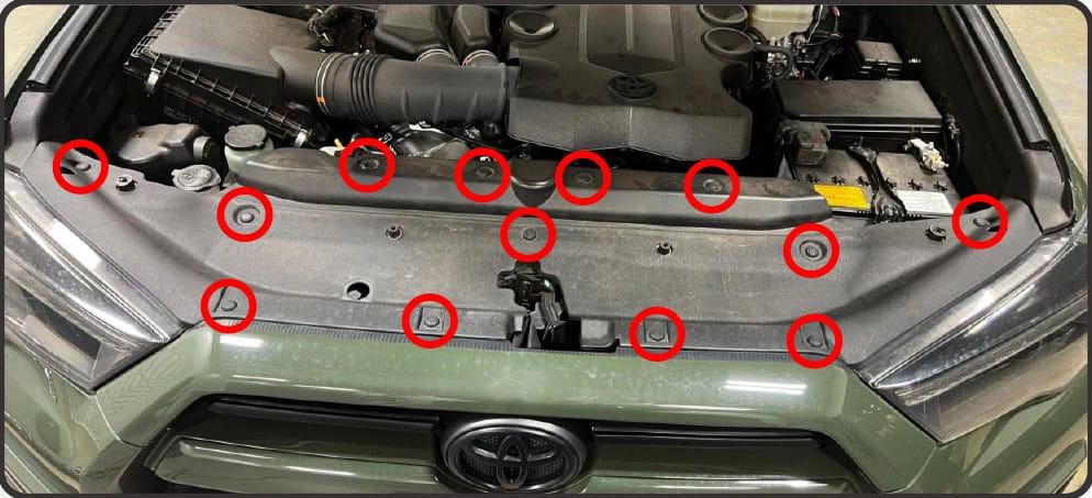
- Open the hood. Remove all thirteen radiator-cover clips and lift off the cover.
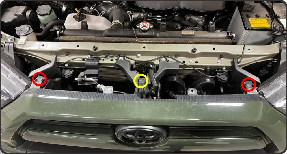
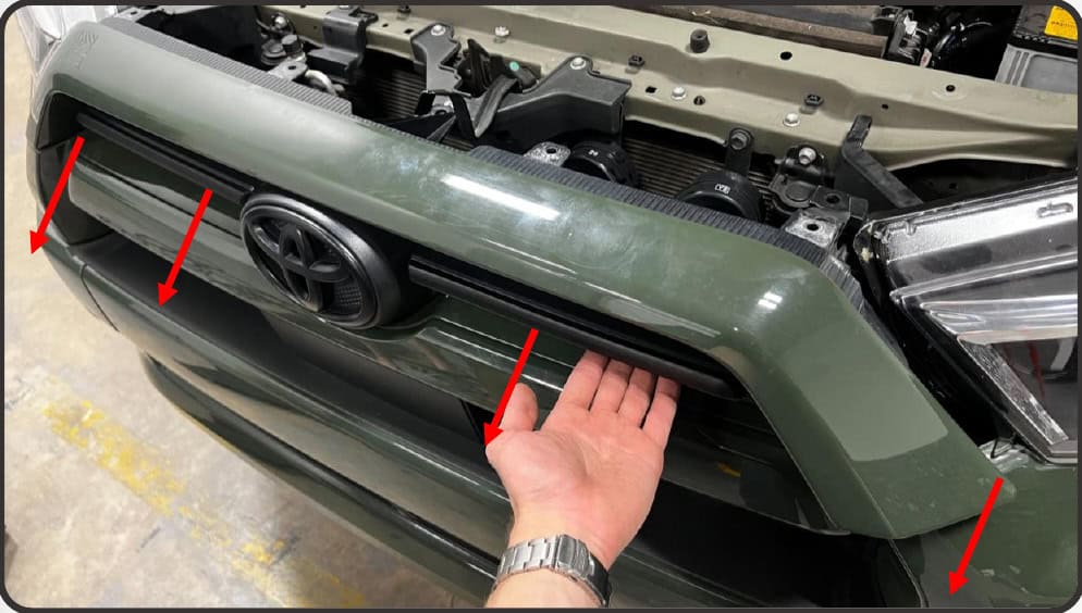
- Remove the two upper-grille clips and central 10 mm screw. Pull the upper grille forward to release its six clips.
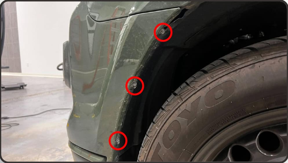
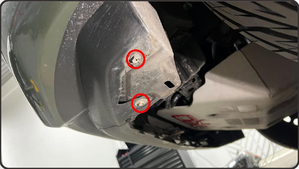
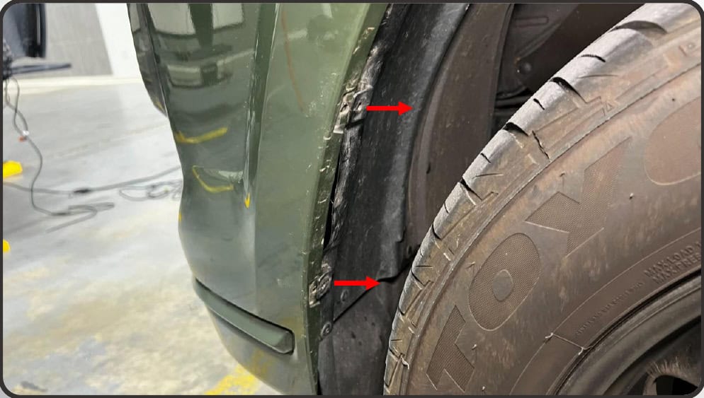
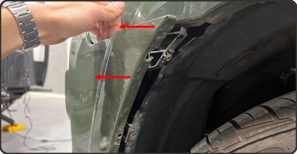
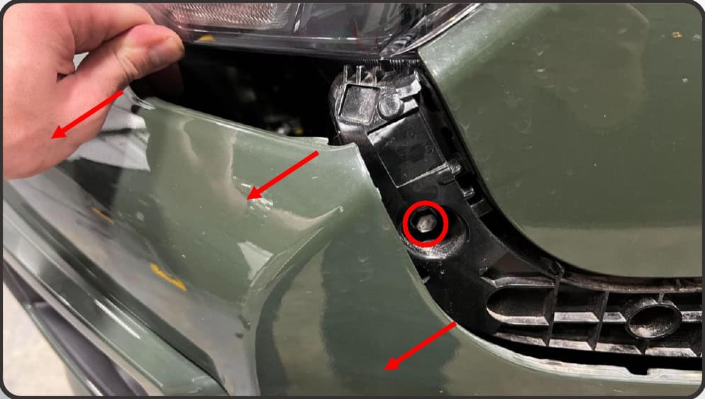
- At the wheel well, remove the three 10 mm screws, then the two lower bumper screws and two fender-liner clips shown.
- Pull the top bumper tab back toward the wheel before pulling the corner away from the fender. Ease the bumper forward enough to release it from the lower headlight bracket.
2. Remove the original lamps and transfer the brackets
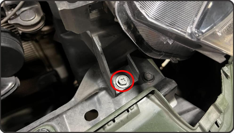
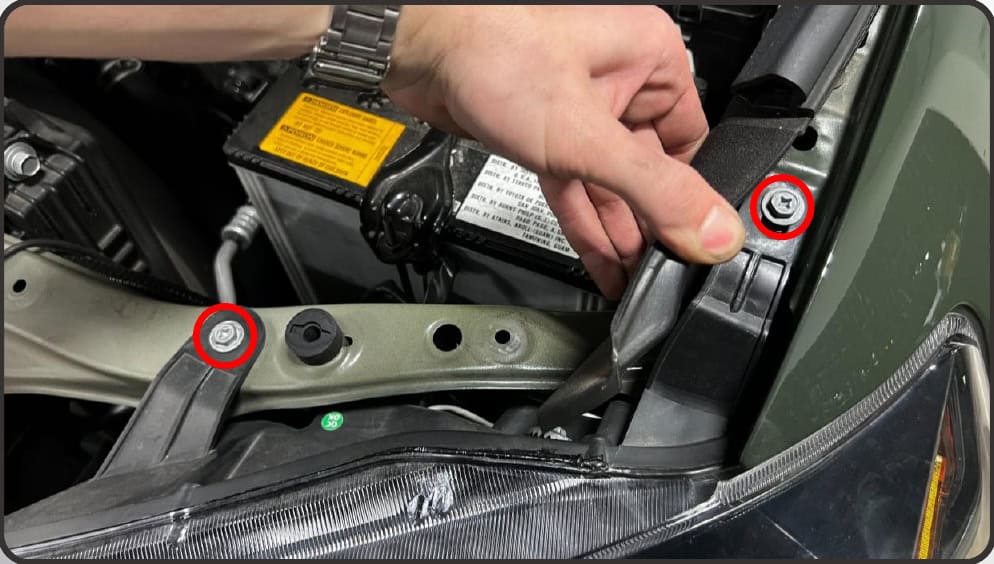
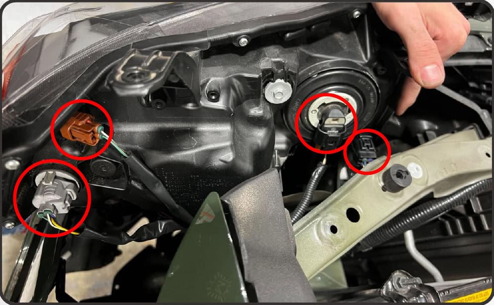
Remove the fender-side and inner headlight bolts, followed by the two upper bolts. Lift the upper tabs, ease the lamp forward and flex the bumper only as needed for clearance. Disconnect the four factory connectors. Repeat on the opposite side.
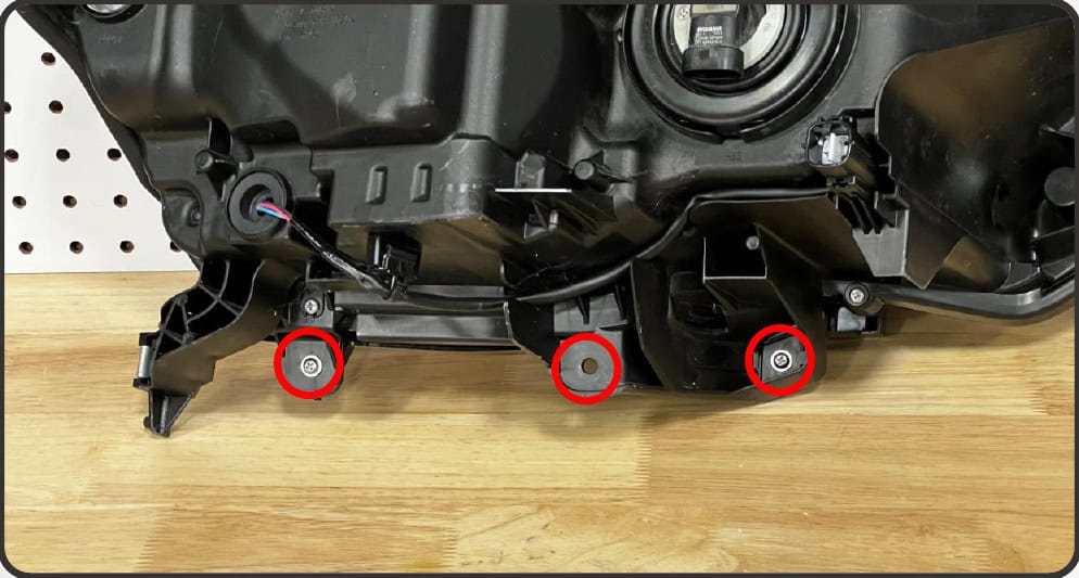
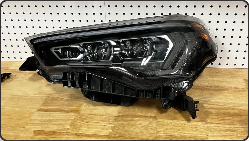
Remove the two or three Phillips screws, depending on the lamp, that hold its lower bumper-cover bracket. Move that bracket to the new headlight using the original screws.
3. Choose the Evo lighting mode
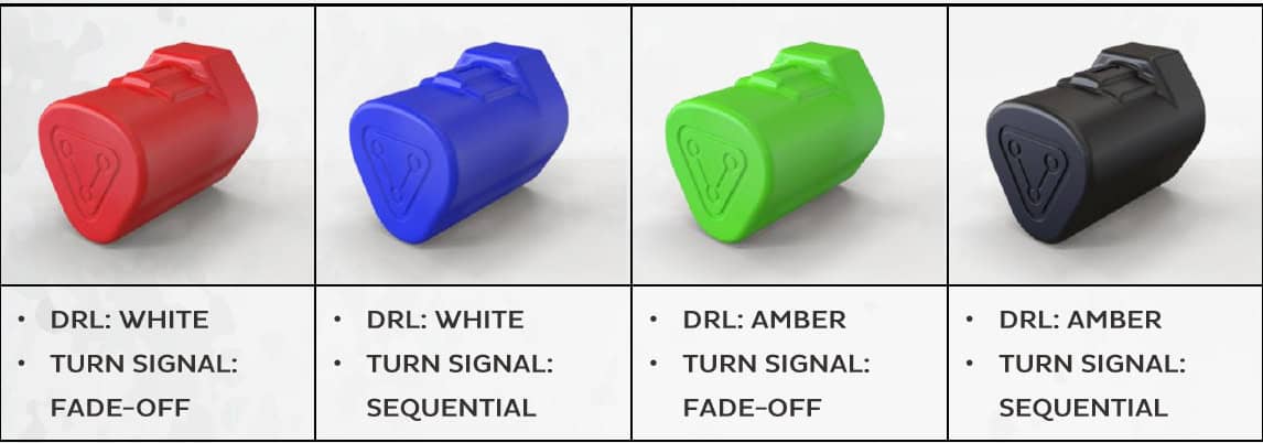
LF2-531 Evo only: choose the same key for both lamps and install it in the rear three-pin connector. Switch the vehicle and lights off whenever changing keys. LF2-531Y Hybrid keeps its fixed white DRL/fade-off setup and does not use these keys.
- Red key
- White DRL · fade-off signal
- Blue key
- White DRL · sequential signal
- Green key
- Amber DRL · fade-off signal
- Black key
- Amber DRL · sequential signal
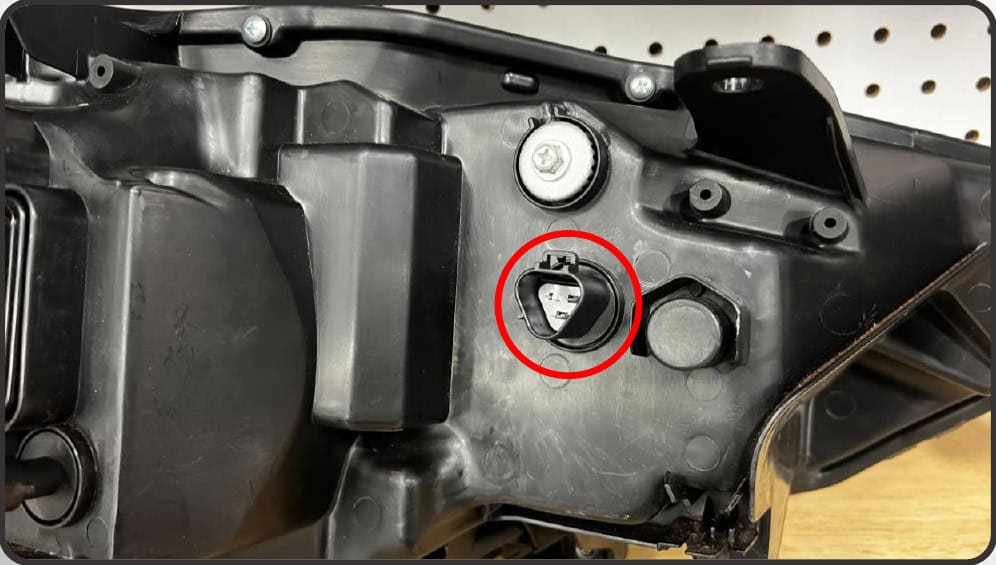
Optional: install the LF2-DRVSC8 driver pair
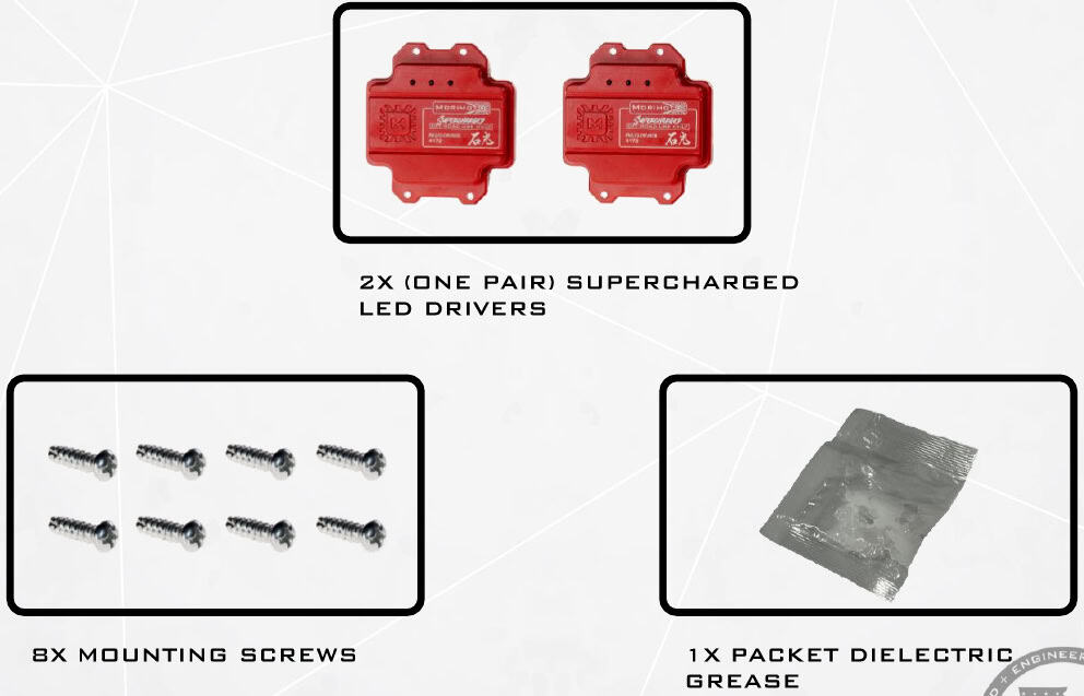
The headlights already include standard drivers. Skip this section for the standard configuration. LF2-DRVSC8 is the separately sold driver pair for LF2-531 and LF2-531Y; the Supercharged configuration is for off-road use only in Canada and the United States.
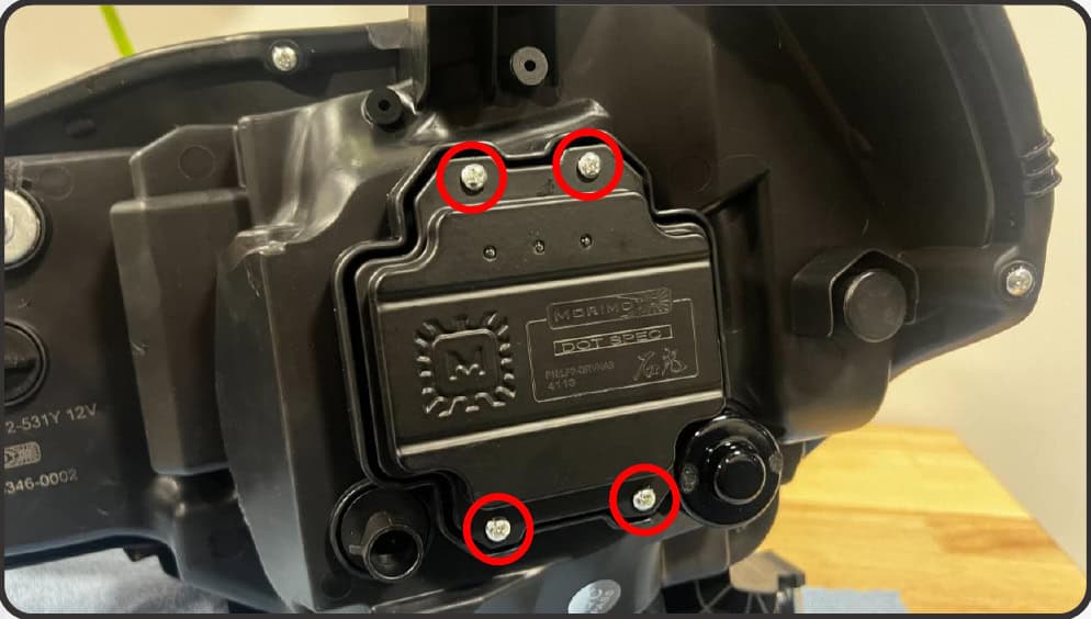
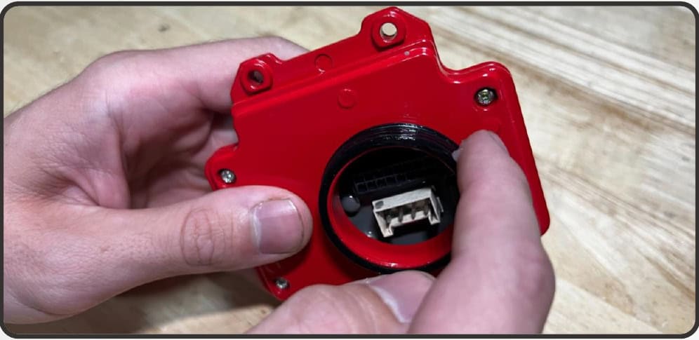
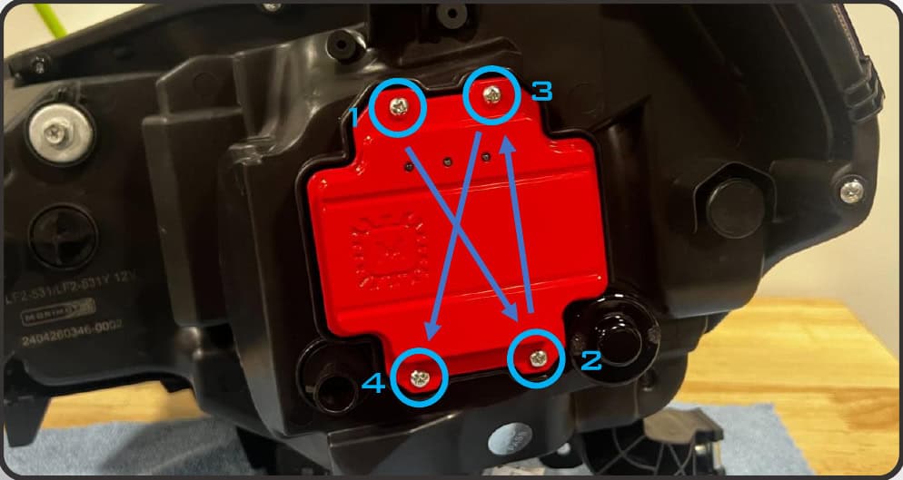
- Remove the four Phillips screws retaining the original driver.
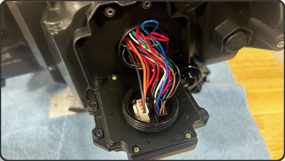
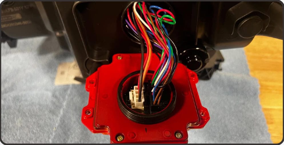
- Lift the driver away, release each connector clip and unplug the internal wiring.
- Apply a thin layer of the included dielectric grease around the outer rubber gasket of the new driver.
- Connect the new driver, checking that every clip locks.
- Press it straight into place without pinching or bunching the seal. Follow the hardware supplied with the driver kit: its SC8 instructions specify four included screws per lamp. Hand-tighten in the illustrated star pattern.
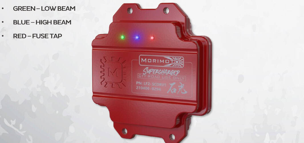
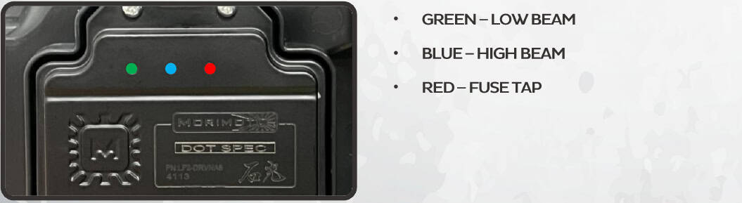
- Repeat on the second lamp. After reconnecting power, green indicates low beam, blue high beam and red fuse-tap power; recheck the relevant connections and fuses if an expected indicator is off.
Open Morimoto’s original SC8 driver instructions (PDF)
4. Use the fuse-feed route for your year
The DRLs and, on heated Evo lamps, the lens heater need switched ignition power: powered while the vehicle is on and off when the vehicle is off. The current Morimoto manual gives two distinct routes.
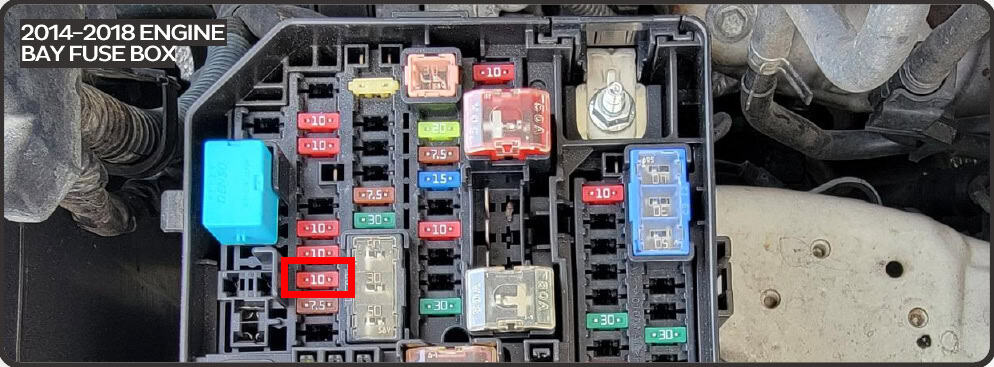
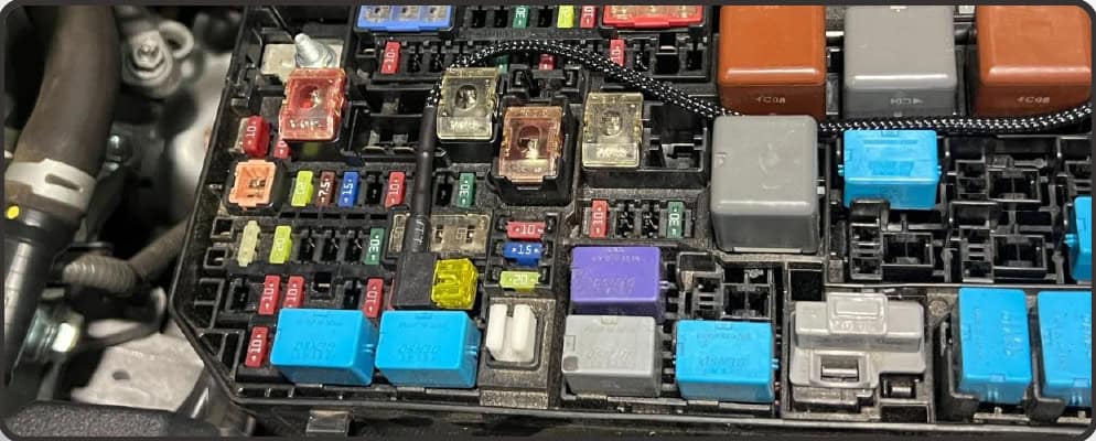
2014–2018: under-hood INJ feed
- Locate the 10 A injector fuse marked INJ in slot 68 of the engine-bay fuse box and remove it.
- Place the removed fuse in the empty slot of the supplied low-profile mini fuse tap. Install the tap in the original INJ position.
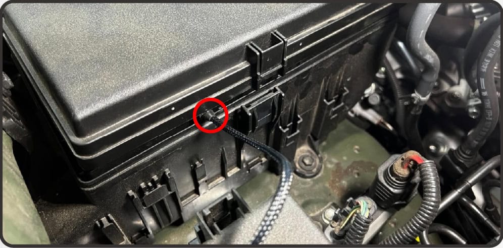
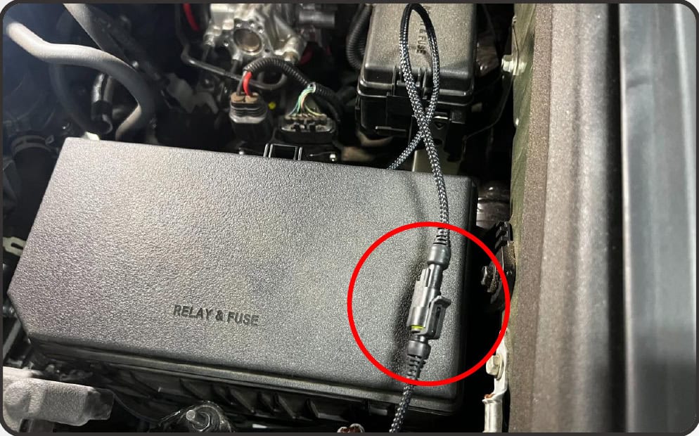
- Make the specified 5.5 mm / 7/32-inch notch in the side of the fuse-box lid. Seat the harness grommet in the notch and close the lid over the routed lead.
2019–2024: interior P/OUTLET feed
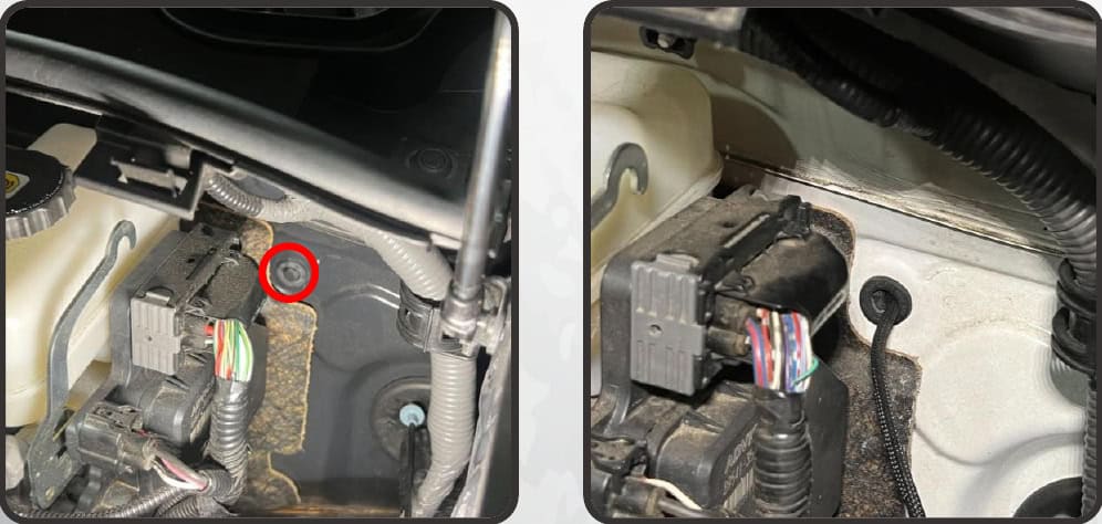
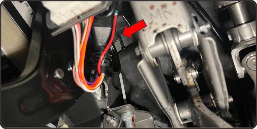
- Remove the firewall grommet shown, cut a slit in its middle and pass the supplied extension through it. Reinstall the grommet in the firewall.
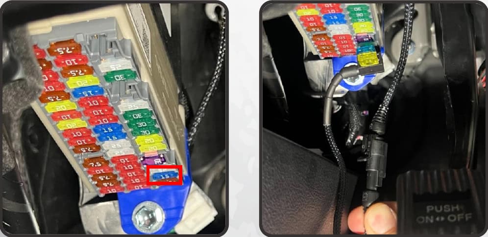
- From the driver footwell, pull the extension down to the interior fuse panel. A second person can help guide it through.
- Locate and remove the 15 A P/OUTLET fuse in slot 47. Fit the supplied fuse tap at that location and connect it to the extension.
- Tuck and secure excess wiring so it cannot be pinched or enter the path of the pedals or other moving components.
This is the newer-year route in the current Evo manual. The under-hood lid-notch procedure above belongs to the 2014–2018 branch.
5. Route the DRL harness
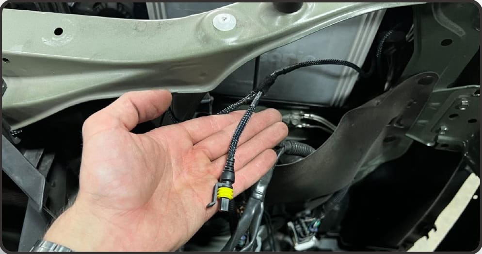
Join the second-longest branch to the fuse tap or its extension. Route the shortest branch to the driver-side headlight. Run the long branch across the top of the radiator support to the passenger side and secure it with zip ties, clear of heat and moving parts.
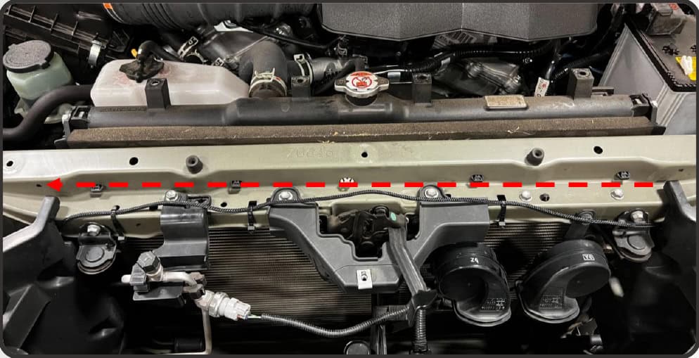
6. Connect the matching equipment adapter
Mount one magnetic resistor in each headlight cavity, out of the way of the lamp.
- Full halogen
- Match the supplied halogen adapter’s four connectors to the four factory plugs; connect the remaining lead to the resistor.
- LED low and LED high
- Use the LED adapter. Its four grey connections go to three vehicle plugs and the resistor. Leave the extra vehicle high-beam connector unused and fit its supplied blank cap.
- LED low and halogen high
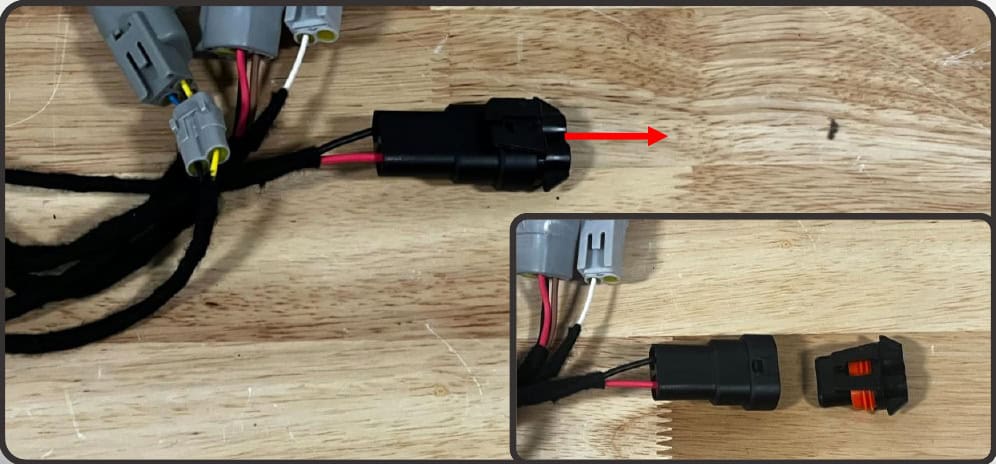
- Remove the cap from the LED adapter’s black connector. Connect all four vehicle plugs and the remaining lead to the resistor.
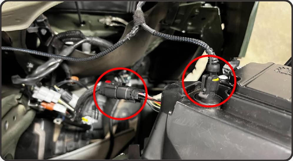
Repeat the correct branch on the other side. Lift each lamp into position, connect the DRL feed and headlight adapter to the back, and secure it with the factory hardware.
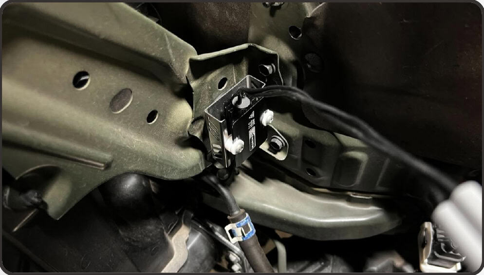
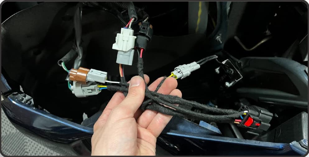
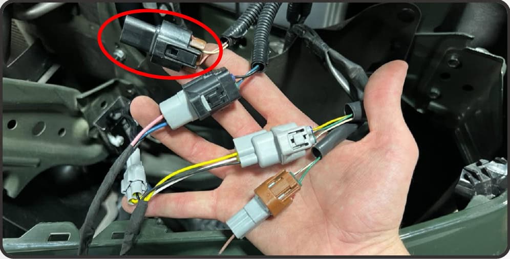
7. Test before reassembly
Check the low beams, high beams, DRLs and turn signals. The rear driver indicators show green for low-beam power, blue for high-beam power and red for fuse-tap power. If an expected indicator is off, recheck its connection and fuse. Once the lighting works correctly, reassemble the front of the vehicle in reverse order.
8. Set the low-beam aim
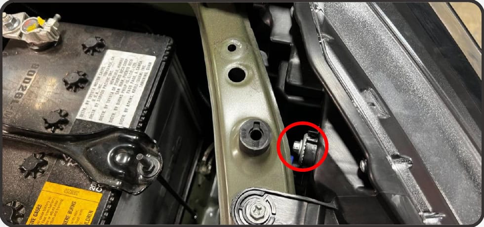
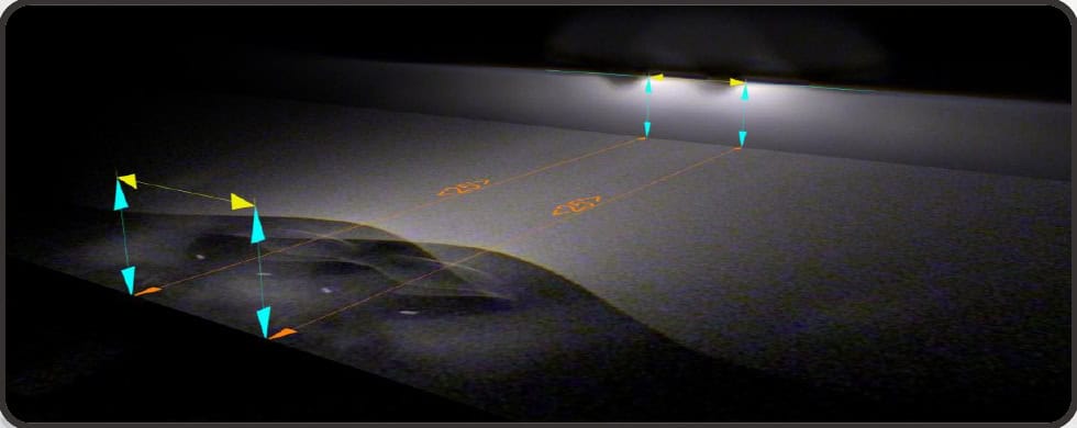
Park on level ground, 25 feet from a wall. Measure from the ground to the optical centre of the outermost projector. Use a long Phillips screwdriver at the rear adjuster to place the upper horizontal cutoff at the height specified below.
- Projector centre below 34.5 inches
- Set the cutoff at the same height as the measured projector centre.
- Projector centre from 35 to 39 inches
- Set the cutoff 2 inches below the measured height.
- Projector centre above 39.5 inches
- Set the cutoff 3 inches below the measured height.
For a measurement between the printed ranges, confirm the aiming specification with BTS or Morimoto before proceeding. Do not turn the adjuster more than three complete turns in either direction; over-adjustment can damage it.
Evo only: request Frost-Free heating
LF2-531 has heating; LF2-531Y Hybrid does not. The heater helps limit snow and ice buildup during cold-weather driving, rather than clearing heavy overnight accumulation.
- With the engine running and the welcome sequence finished, flash the high beams four times within four seconds.
- Two response flashes: heating is active. One response flash: the request is acknowledged, but the system is waiting for its operating conditions.
- Once requested, the system regulates itself until the ignition is switched fully off or you disable it. It defaults off at every new ignition cycle.
- To disable manually, repeat four flashes within four seconds. One flash acknowledges the request.
The ambient sensor must read at or below 5°C / 41°F. Lens temperature, heating-element temperature and battery voltage also govern operation. If the request is not recognised, turn off automatic high beams and try the request again.
Watch the manufacturer installation
Use the current written fuse-feed branches above alongside the video.
Matching headlights and help
4Runner XB Evo headlights
View the exact product and its included equipment.
4Runner XB Evo Hybrid headlights
View the exact product and its included equipment.
LF2-DRVSC8 Supercharged drivers
View the exact product and its included equipment.
4Runner Frost-Free overview
Compare the headlight features and original-equipment fitment.
Original instructions
Original BTS explanatory text, based on Morimoto’s LF2-531/LF2-531Y 24-page installation manual and the linked four-page Supercharged-driver manual, retrieved October 24, 2026. Manufacturer illustrations are retained with their original annotations. No printed revision date was found in these PDFs.