

BTS INSTALLATION GUIDE · MORIMOTO XBG36
2014–2024 Toyota 4Runner XBG grille installation
Fit the grille and four 2Banger pods, select the correct backlight-power route, then connect the separate main-beam controls. The original Morimoto figures below show the mounting points and wiring without changing their annotations.
Before you begin
This guide is for the Morimoto XBG36 grille on the 2014–2024 Toyota 4Runner. Morimoto illustrates the process on a 2021 SR5; existing equipment and earlier modifications can affect access. Review the original manual and diagrams first, and use a qualified installer if the wiring or disassembly is unfamiliar.
2020 models: check the original center-bracket and spacer arrangement with BTS before assembly. Use the matching hardware branch below rather than forcing a mismatched bracket into place.
Have a ratchet with 10 mm socket, trim-pry tool, T20 Torx driver, #2 Phillips screwdriver, zip ties, detail cleaner and isopropyl alcohol available. The 2014–2018 fuse-box route uses a 5.5 mm / 7⁄32-inch notch. Installing the supplied cabin button uses a ¾-inch mounting hole.
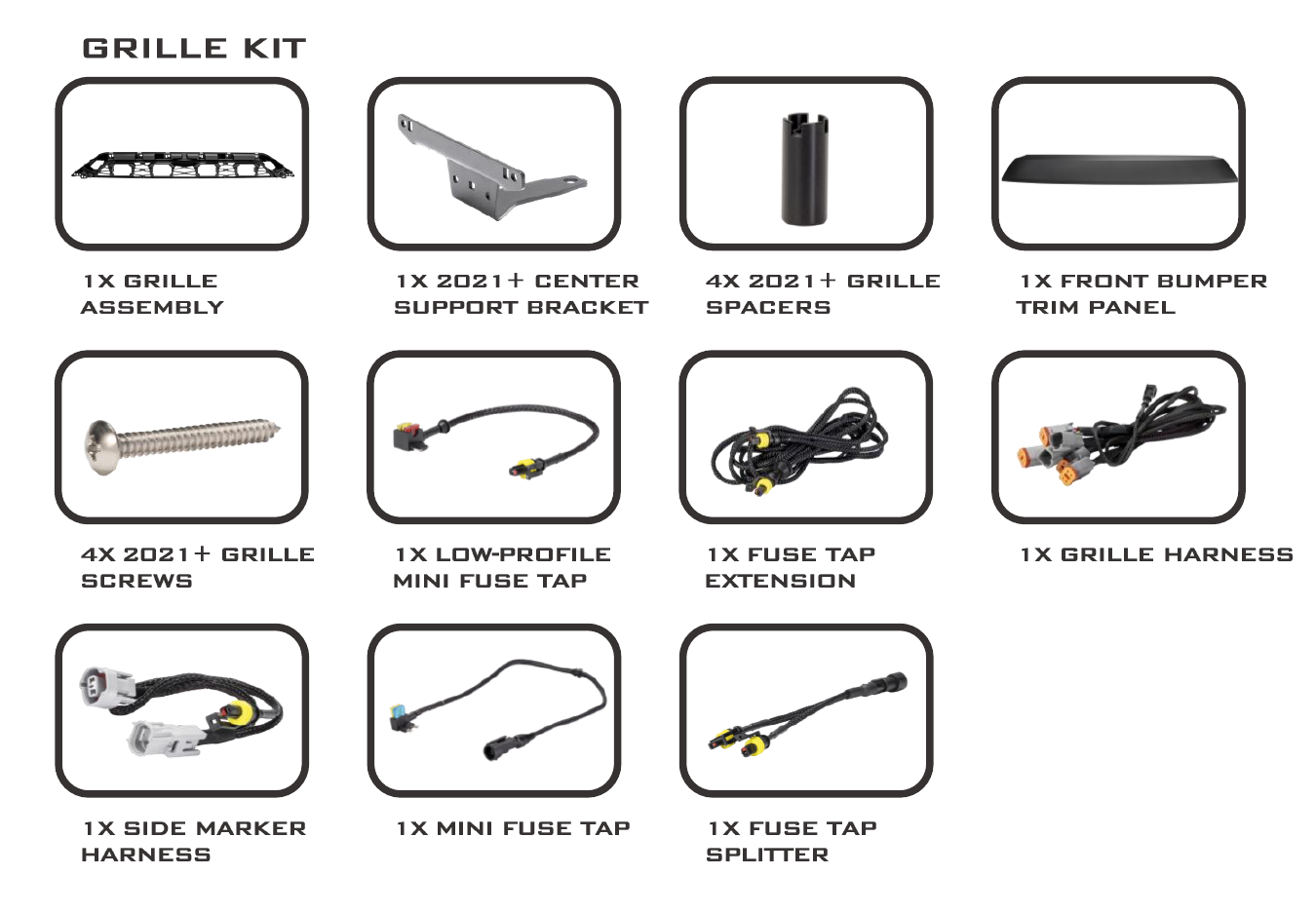
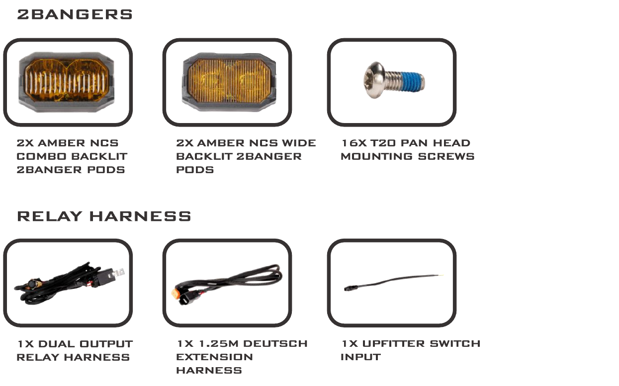
Lay out the grille, fascia, hardware, four pods and wiring before removing the original parts. Keep the factory screws and clips for reuse.
1. Remove the upper grille
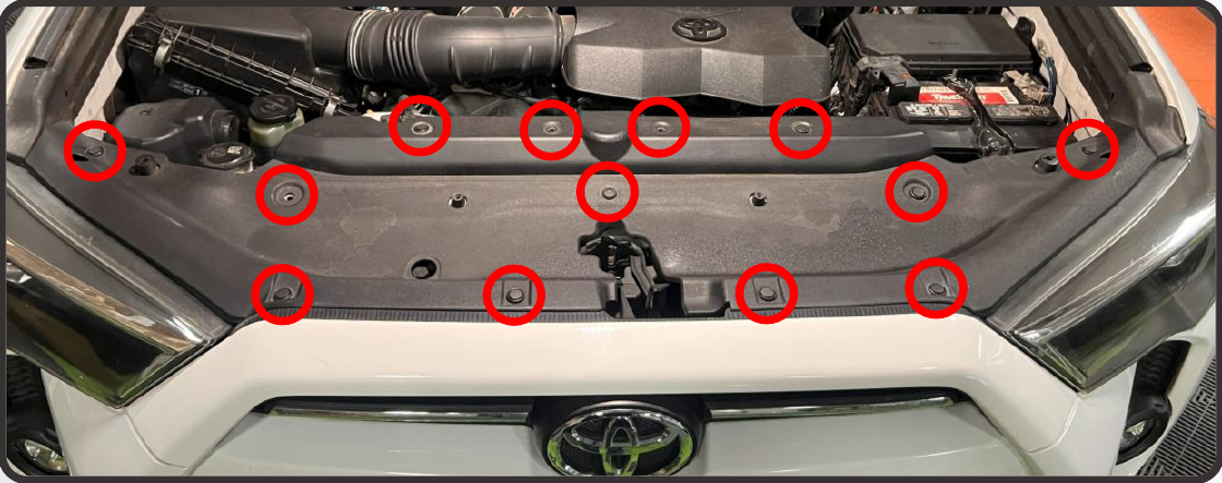
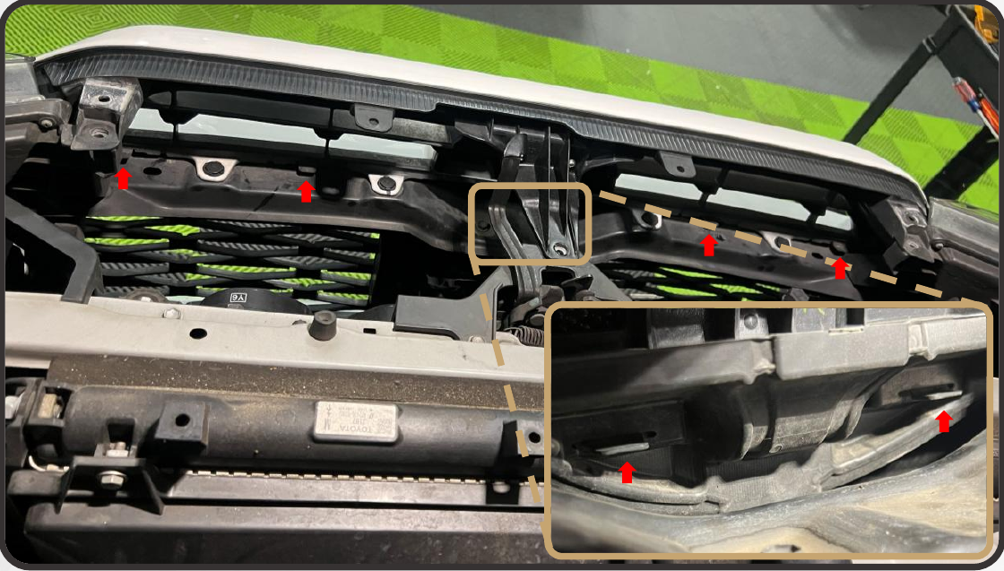
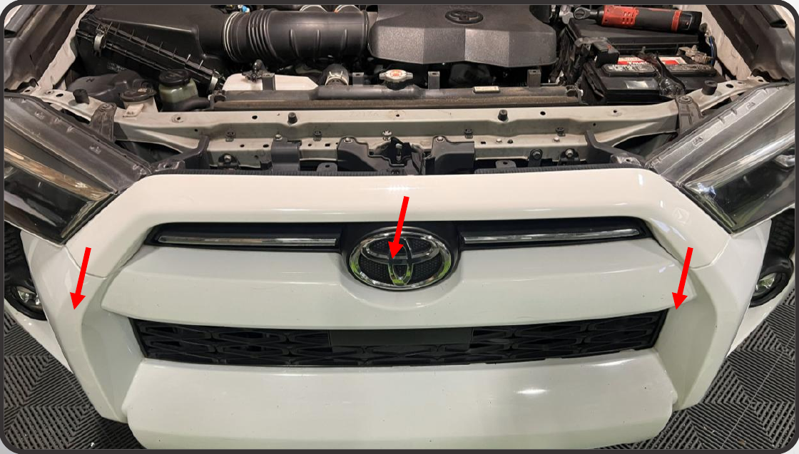
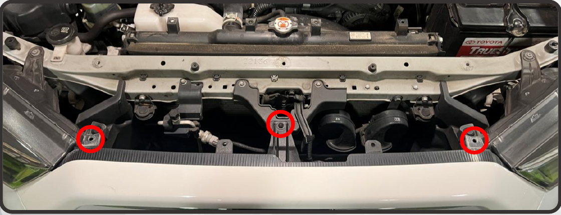
Raise the hood. Depress the centers of the thirteen radiator-cover push clips, lift their outer portions and remove the cover. At the top of the grille, release the two push clips and remove the central 10 mm fastener.
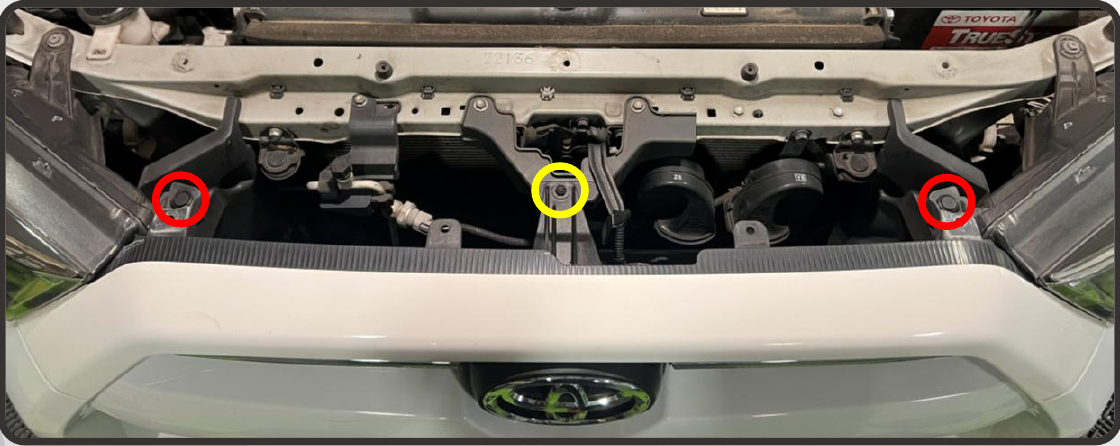
Lift each of the six tabs along the grille’s bottom edge while drawing the grille forward. Once the tabs release, pull the upper grille away from the vehicle.
2. Transfer the surround and fit the pods
Place the removed grille face-down on a towel or soft mat. Remove the eight Phillips screws, four on each side. Release the two clips on each side and separate the surround.
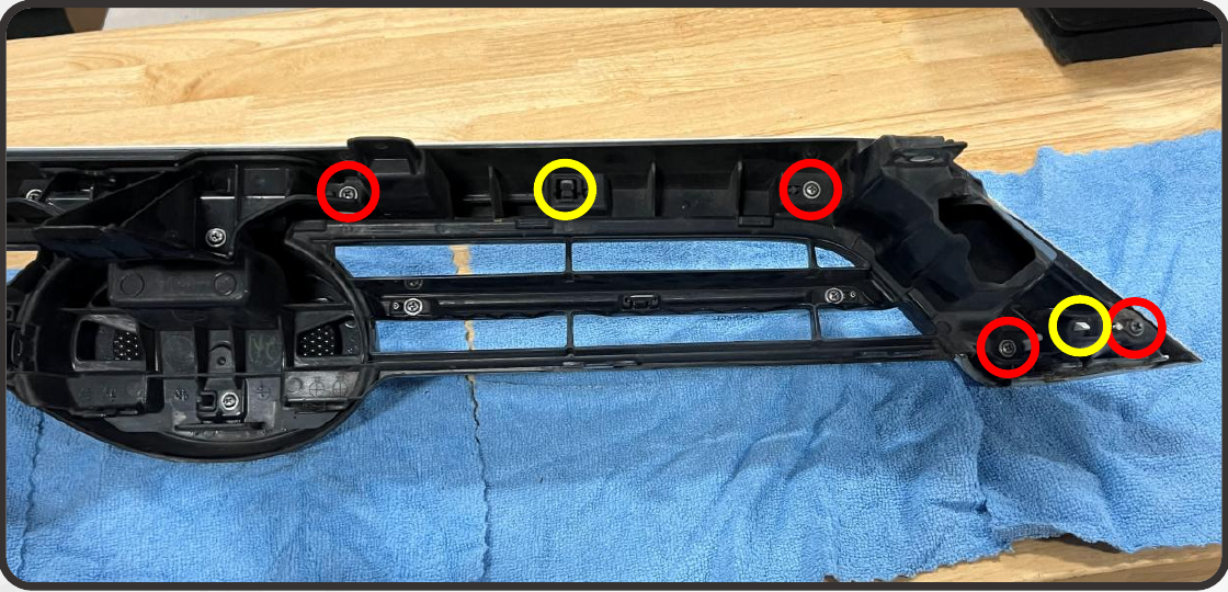
The manual’s older-hardware branch transfers the original center bracket: remove its two mounting screws and retain the bracket. Its newer branch uses the supplied replacement bracket.
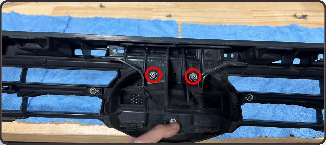
Center-support hardware branches
2014–2019: follow the original-bracket branch. 2021–2024: follow the included-bracket and spacer branch. 2020: confirm the original arrangement before choosing a branch.
For the included-bracket branch, fit the taller spacers to the outer standoffs marked red and the shorter spacers to the inner positions marked yellow. Clip the new grille into the original surround. Refit the six outermost Phillips screws; use two supplied longer screws at the inner positions shown for the newer branch.
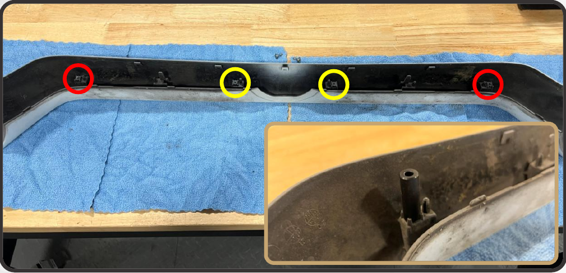
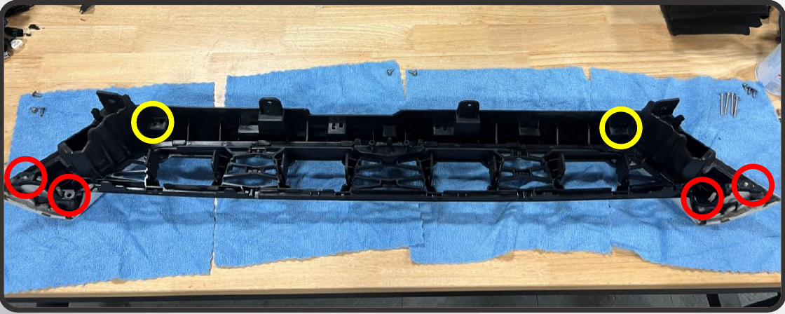
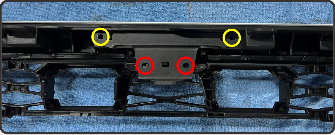
Fit the center support. With the original-bracket branch, reuse the four factory screws identified by the manual. With the included-bracket branch, use two original screws in the lower holes and two supplied extended screws through the upper holes and spacers.
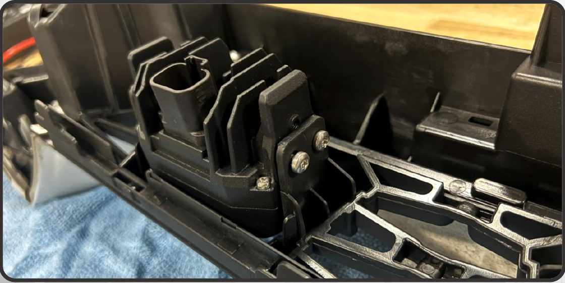
Place the four pods in the grille openings. Each pod uses two T20 screws on each side, sixteen screws in total. Hand-tighten them enough to hold the pods while allowing the aim to be adjusted.
3. Fit the fascia and reinstall the grille
If the vehicle has the original Toyota oval front badge, fit the included black fascia panel. Clean dirt from the center bumper surface, then wipe it with isopropyl alcohol to remove wax and oil. Peel the adhesive backing from the panel.
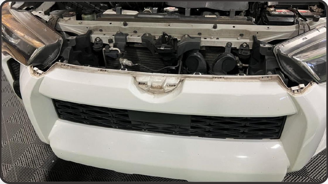
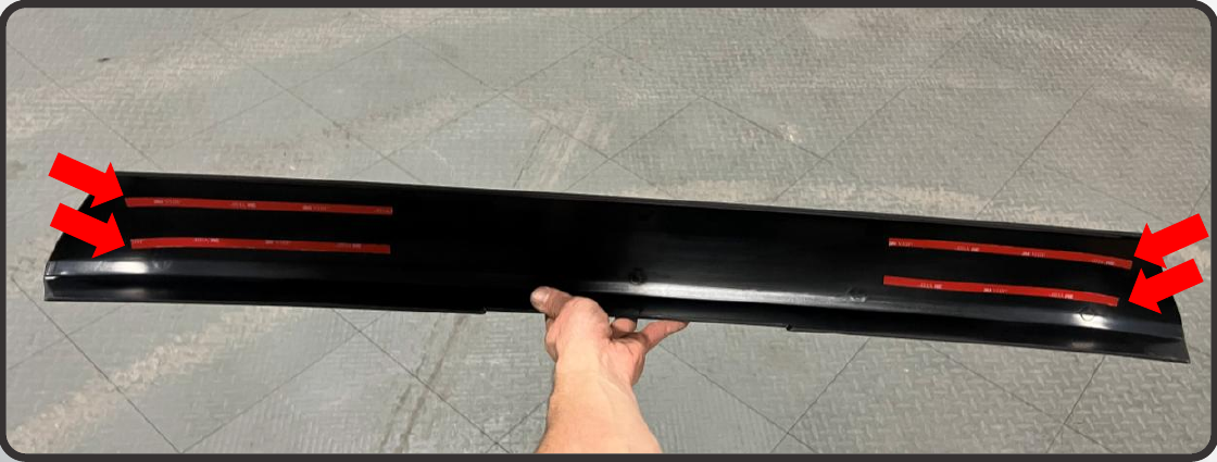
Center the panel over the bumper and press firmly for a few seconds to seat the adhesive. Refit the grille, engaging all six lower clips, then install the two original upper push clips and central 10 mm fastener.
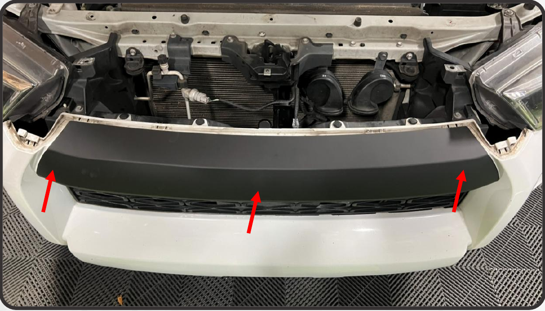
4. Choose the backlight-power route
The backlights need switched ignition power: on with the vehicle and off when the vehicle is off. Choose only the route for the vehicle’s year.
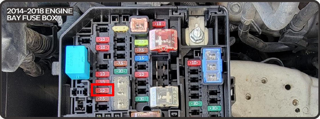
2014–2018
Underhood fuse box: 10 A INJ, slot 68. Use the low-profile mini fuse tap.
2019–2024
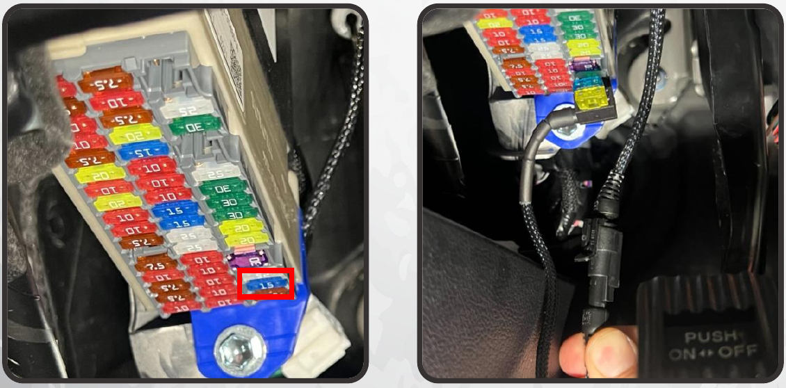
Interior fuse panel: 15 A P/OUTLET, slot 47. Use the standard mini tap and extension through the firewall.
2014–2018: underhood route
Open the underhood fuse box and remove the 10 A INJ fuse from slot 68. Place that fuse into the empty fuse position on the low-profile mini tap, then install the tap in the vacated INJ position.
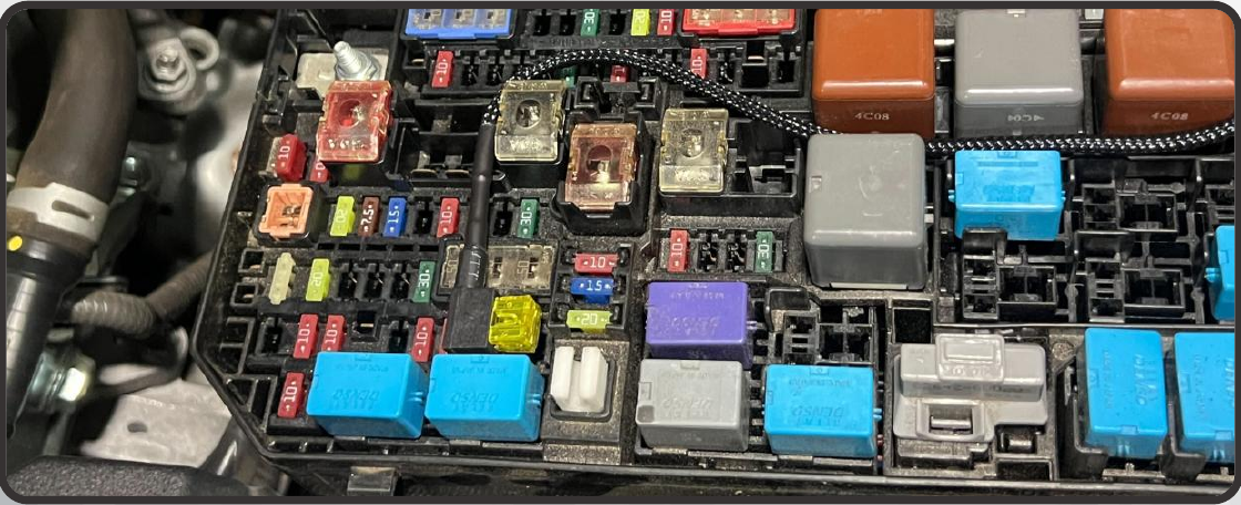
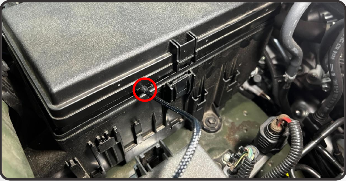
Route the lead through the side of the fuse-box lid. Make the specified 5.5 mm / 7⁄32-inch notch, seat the harness grommet in it and close the lid over the routed harness.
2019–2024: interior route
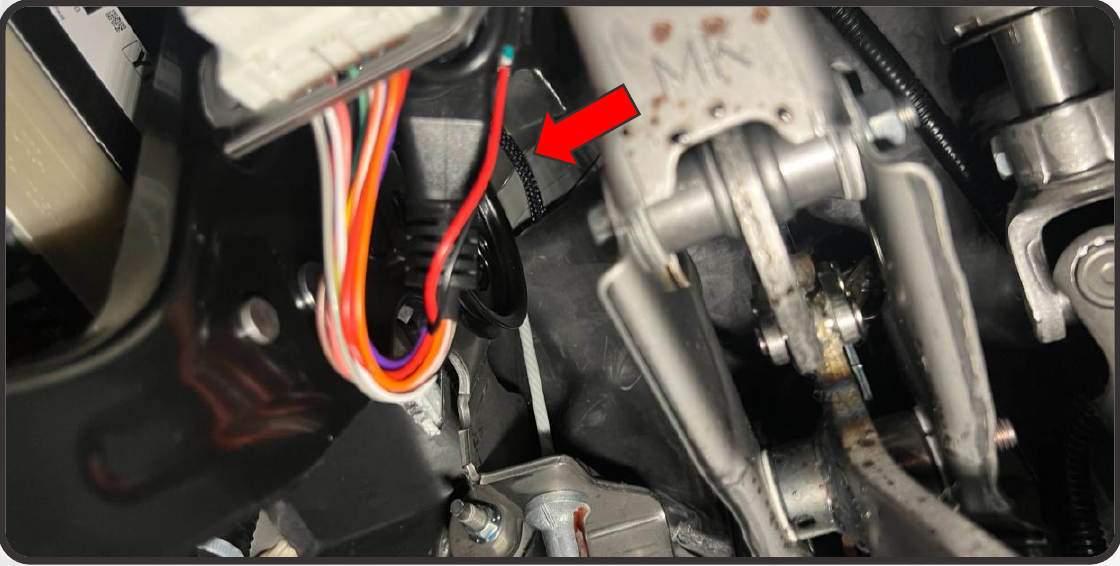
Remove the firewall grommet shown below, make a slit in its center and pass the supplied fuse-tap extension through it. Refit the grommet.
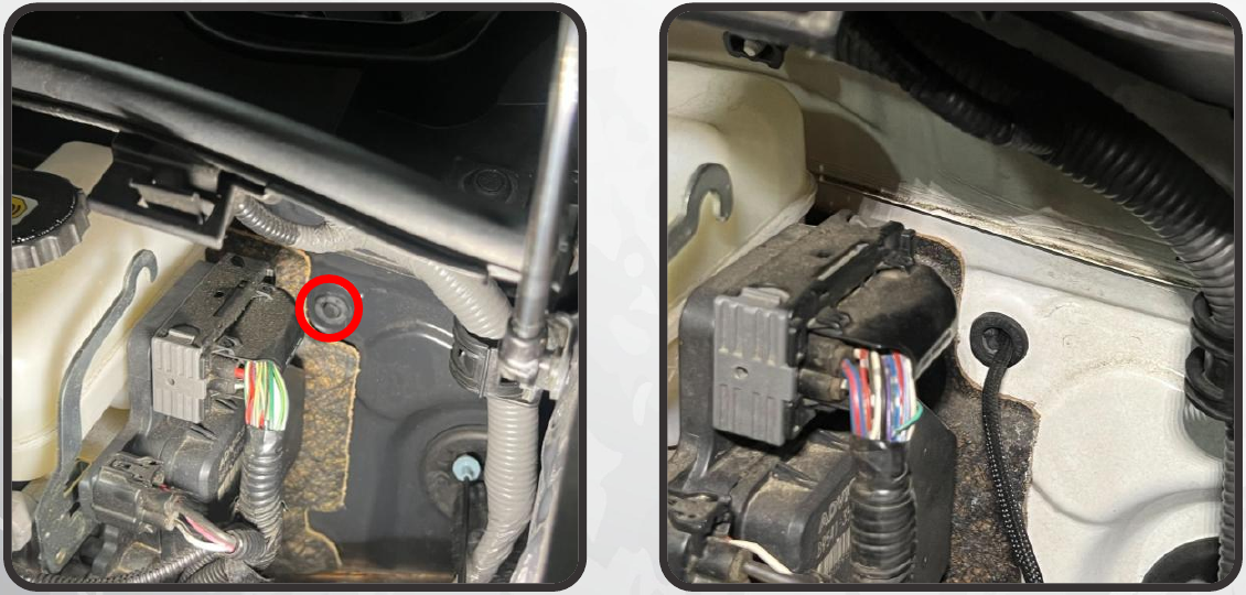
From the driver’s footwell, locate the extension and draw it toward the interior fuse panel. A helper can guide it through from the engine bay.
Locate the 15 A P/OUTLET fuse in slot 47 and fit the supplied standard mini tap, following the original wiring diagram and supplied tap instructions. Connect it to the extension. Tuck and secure excess wiring so it cannot be pinched or interfere with any pedal movement.
5. Connect the backlights, dimmer and main beams
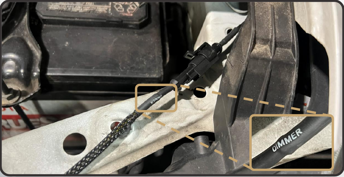
Connect the fuse tap or extension to the grille-harness plug marked BACKLIGHT. If Morimoto XB headlights share this feed, connect the supplied splitter first: one output goes to BACKLIGHT and the other to the headlight DRL harness.
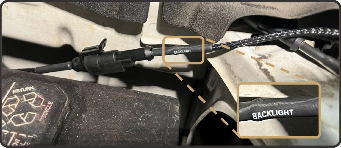
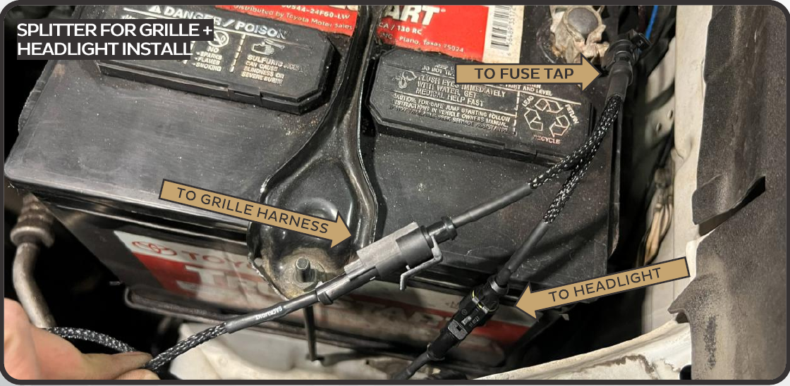
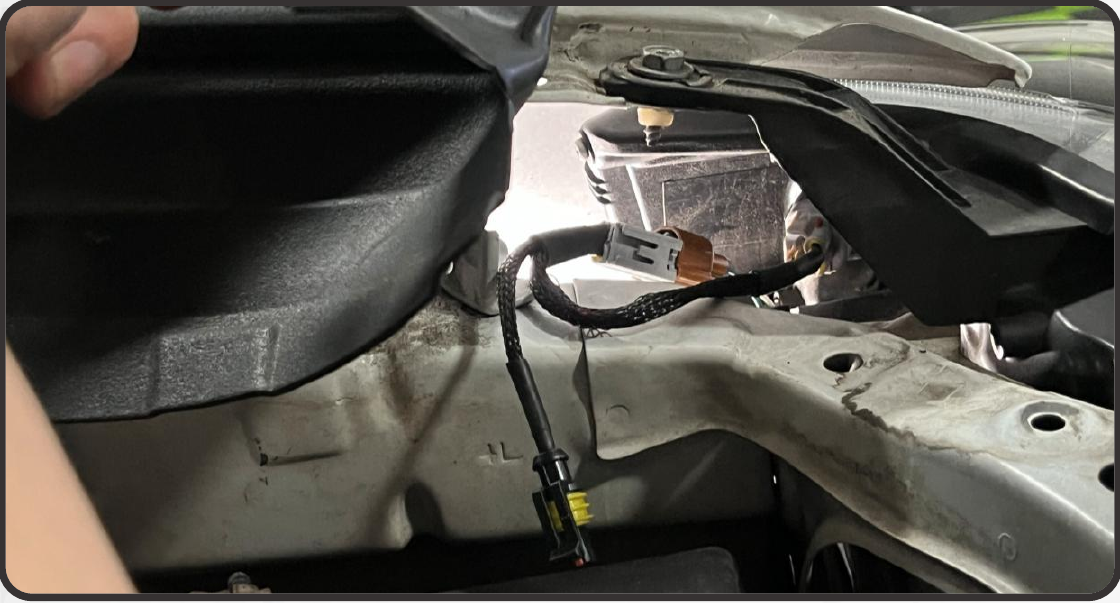
Pull back the rubber trim along the inner fender to reach the headlight side-marker connector. Disconnect it and insert the supplied side-marker harness between the vehicle connector and headlight. Connect its single-pin output to the grille-harness plug marked DIMMER.
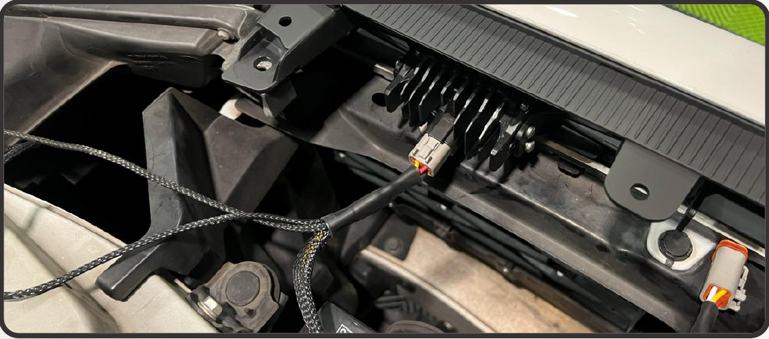
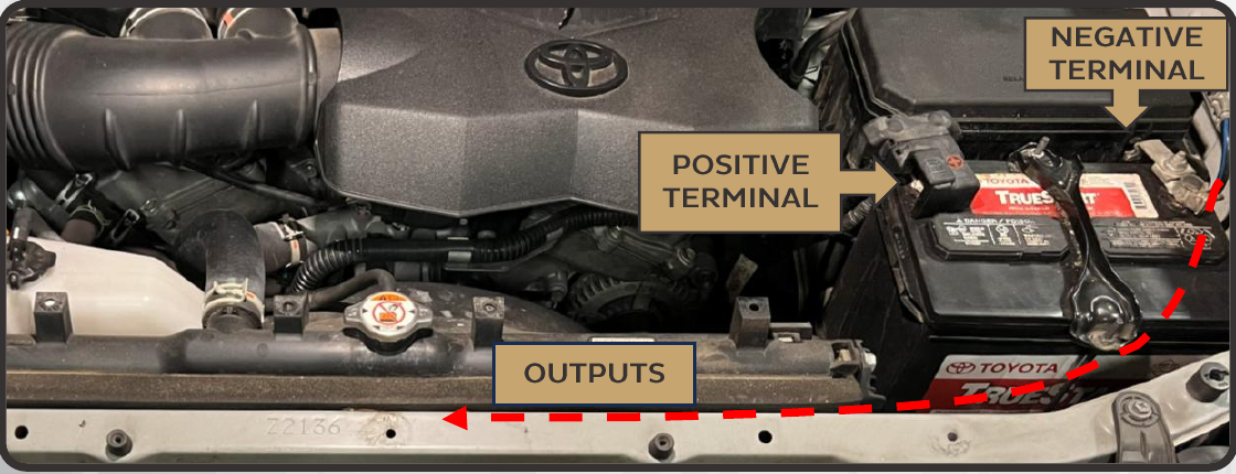
Plug the four 4-pin DT connectors into the four pods. Lay out the relay harness in the engine bay. Connect its ring terminals to the corresponding positive and negative battery terminals, mount the relay upright near the battery and route its outputs toward the center of the radiator support.
Choose one main-beam control
- Existing switch system: connect the supplied trigger input to the intended upfitter-switch output using the original wiring diagram.
- Included push button: route the button into the cabin through the firewall grommet used above. Check the proposed mounting location, then use a ¾-inch hole for the button.
Connect the two relay outputs to the two grille inputs; either output can feed either input.
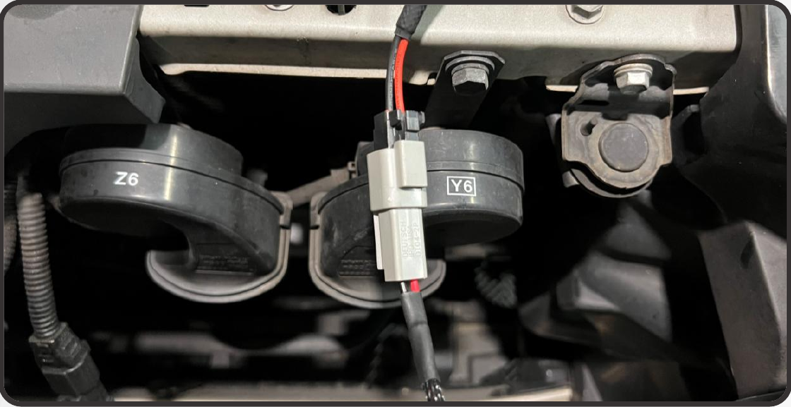
6. Test, secure and finish
Check the daytime backlights, the dimmed backlights with the parking-light circuit and the separate main beams. Adjust the pods within the grille’s ±6° range and secure their mounting screws after aiming.
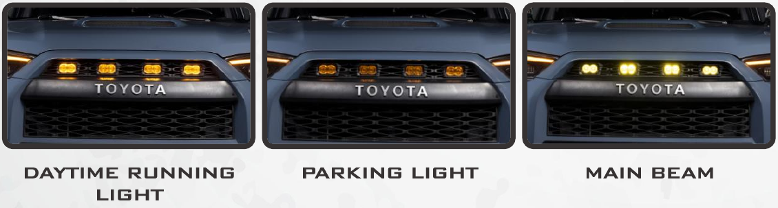
Secure loose wiring with zip ties. Keep every lead clear of fans, belts, exhaust components and other moving or hot parts; check the footwell for pedal clearance again. Reinstall the radiator cover. The grille’s auxiliary main beams are for off-road use.
7. Use the diagram for your headlights
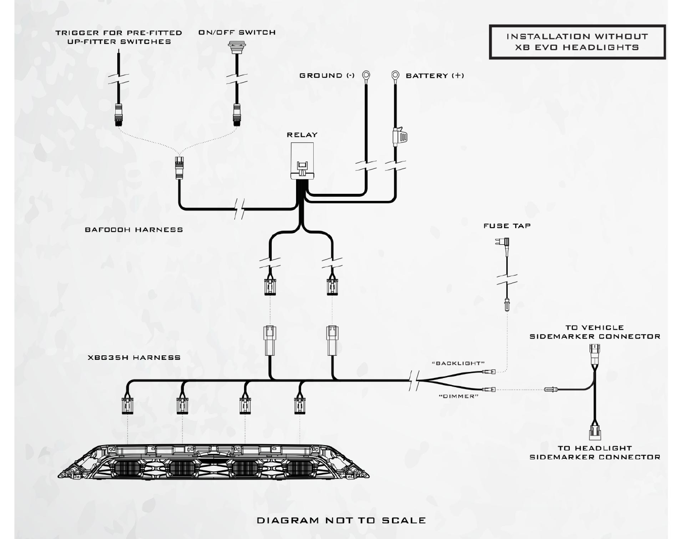
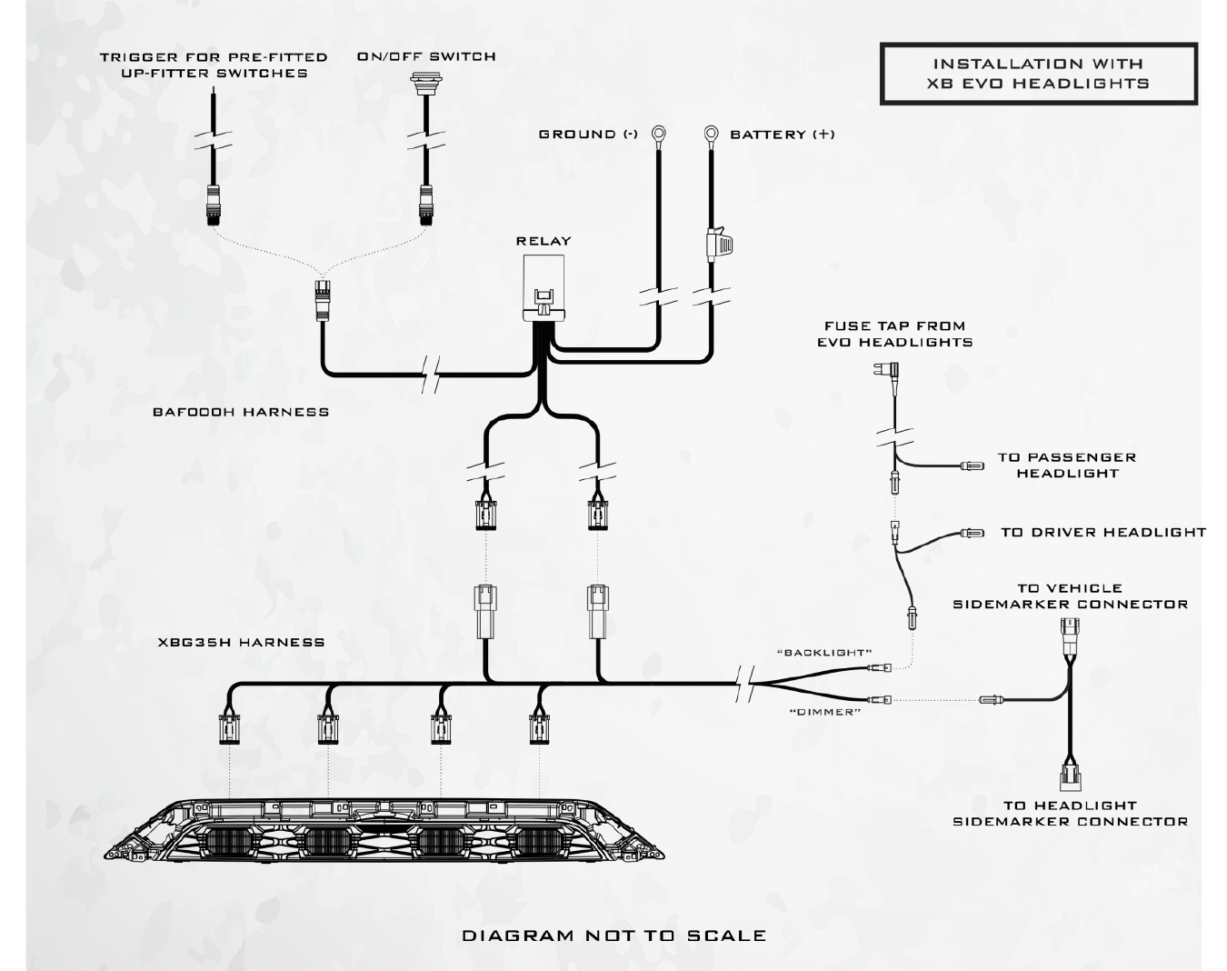
Open either drawing at full size to follow the connector labels. These are the original manufacturer diagrams; their printed “not to scale” note and annotations are retained.
Stock headlights
Morimoto XB Evo headlights
Video, original manual and matching kit
Morimoto’s 4Runner XBG grille video.
Open the original 20-page Morimoto manual
Morimoto XBG36 grille for the 4Runner
Return to the complete grille kit, included parts and current buying options.
Explore 2014–2024 4Runner lighting upgrades · Read the 4Runner lighting buying guide
Original BTS instructions based on Morimoto’s XBG36 installation manual and current product information, reviewed October 24, 2026. Technical photographs and wiring diagrams are reproduced from the manufacturer’s manual. The captured PDF has no visible revision date; retain the manual supplied with your kit.