

BTS installation guide
Install JL SS5 bumper pods or a four-pod grille bar
The vehicle brackets share the frame-rail work. After fitting the rivnuts and base brackets, follow the correct two-pod or linked-bar mounting branch.
Prepare the vehicle and tools
For 2018–2026 Jeep Wrangler JL. A 2018 Wrangler can be JK or JL; confirm the generation. Check aftermarket bumper, winch, fairlead and accessory clearance against the mounting diagram before ordering. Installation photos may show other lights that are not included.
Prepare a trim tool, 3/8-inch ratchet, 5/8-inch socket, 10 mm socket and wrench, drill with 10 mm (25/64-inch) bit, and 4/5 mm Allen tools. The original two-pod/grille manual removes the plastic bumper cover and does not reinstall it.
Remove the bumper cover and grille
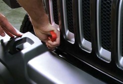
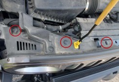
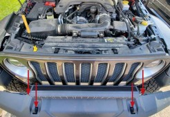
Release the two bumper-bar rivets and six forward-facing bumper-cover rivets; remove the plastic cover. Remove the six upper grille push-rivets. Lift the grille over obstructions and pull straight forward from the lower inside edges of the headlight openings and grille.
Enlarge the holes and set the M6 rivnuts
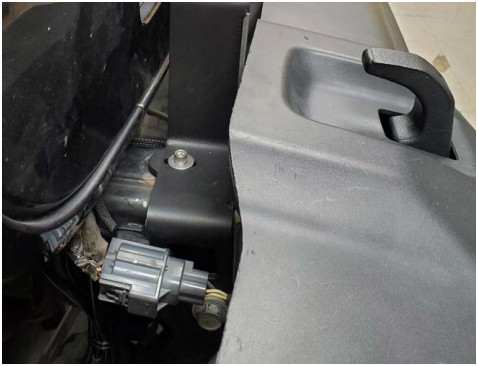
Enlarge the existing top frame-rail hole on each side to 10 mm. Remove the passenger-side connector holder and retain it for reinstallation. Remove and retain the outboard bumper bolt with a 5/8-inch socket. The original photograph marks the drill hole yellow and the bumper bolt red.
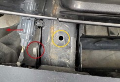
Use a suitable rivnut tool, or the supplied 40 mm M6 setting screw, nut and washer. Assemble them through the base bracket with full rivnut thread engagement. Seat the rivnut in the enlarged hole and temporarily secure the bracket with the retained bumper bolt.
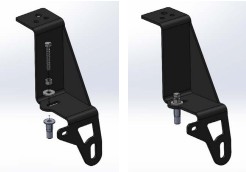
Hold the screw still while turning the nut clockwise down the screw to set the rivnut. When it stops turning, remove the setting hardware and bracket. Thread the screw loosely into the rivnut and pull outward to confirm secure retention. Repeat the setting procedure if it pulls free, then complete the other side.
Refit the grille and choose the correct lamp branch
Reinstall the grille. Secure both base brackets with the retained bumper bolts plus the supplied 20 mm M6 screws and oversized washers. The passenger-side tab retains the original connector holder.
Two-pod bumper kit: install each pod separately using its universal mount and hardware on the base bracket. There are no CrossLinks between these two lamps.
Four-pod grille kit: install the CrossLink universal brackets with the 16 mm M6 screws, washers and flange nuts. Assemble the four-pod bar using the SS5 CrossLink assembly, wiring and backlight guide, then mount it loosely with the supplied M6 hardware for adjustment.
Connect the supplied fused harness
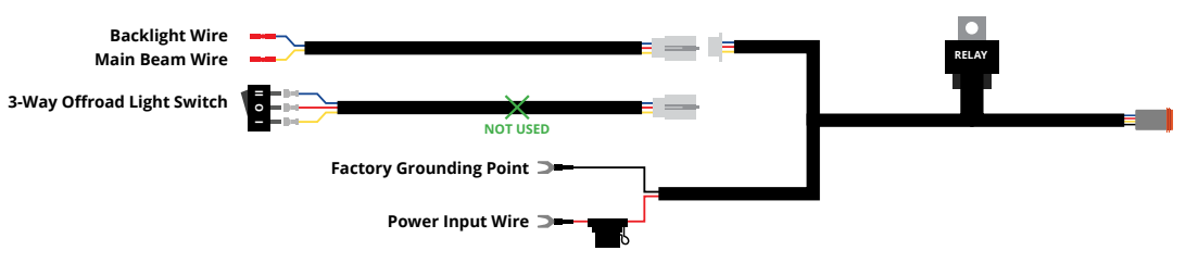
Route the harness through the engine bay. Follow the exact harness supplied with your kit: the original relay-harness diagram shows separate main-beam and backlight controls, battery/power input and ground. For the factory AUX branch, crimp the yellow main-beam control and blue backlight control to the selected auxiliary leads. Without factory AUX switches, use the supplied toggle-switch adapter. Connect the main positive and negative power wires as instructed, keep all sources fused, secure the loom and test before final adjustment.
White-lens kits produce a 6000K main beam and allow eight selectable backlight colours. Yellow-lens kits produce a 3000K main beam and Amber backlight only. Backlight programming changes the accent, not the main-beam colour. Use these auxiliary lights only where permitted.
The SS5 CrossLink assembly, wiring and backlight guide covers backlight programming and reset. Yellow lenses remain Amber-only.
Use the branch that matches the two-pod bumper kit or four-pod grille bar.
Parts and original instructions
Two-pod bumper kits · Bumper brackets only · Four-pod grille kits · Original exact-SKU PDF · Current manufacturer grille article