

BTS fog-light installation
Install SS3 fog lights in the correct Jeep bumper
Use the Type M, MR or MS procedure for the actual fog-light mount. The Sport plastic bumper has a different removal sequence.
Identify the bumper and lamp first
| Mount | Application | What changes |
|---|---|---|
| Type M | Matching non-Sport plastic mount | Standard Type M bracket |
| Type MR | Matching factory steel mount | Steel adapter added to Type M bracket |
| Type MS | JL/JT Sport plastic mount | Three-screw bracket and Sport bumper access |
These are replacements for factory fog-light locations. Match the bumper, lamp mounting points and electrical connector before ordering. A vehicle without factory fog lights needs a separate mounting and wiring plan. Check clearance and compatibility with an aftermarket bumper.
Use hand tools. Prepare a 5/32-inch Allen key; the Type MS Sport procedure also uses a trim tool, 8mm and 7mm sockets and a T20 Torx driver. Secure the vehicle and switch the lamps off before disconnecting wiring. Refer to the selected product for exact vehicle years and restrictions.
Type M and MR: assemble and replace the factory lamps
1. Assemble the pod bracket. Place the supplied locking nuts in the pod housing with the nylon facing inward. Fit the bracket with the supplied screws and washers. Tighten until the pod holds its position but can still pivot with force for aiming.
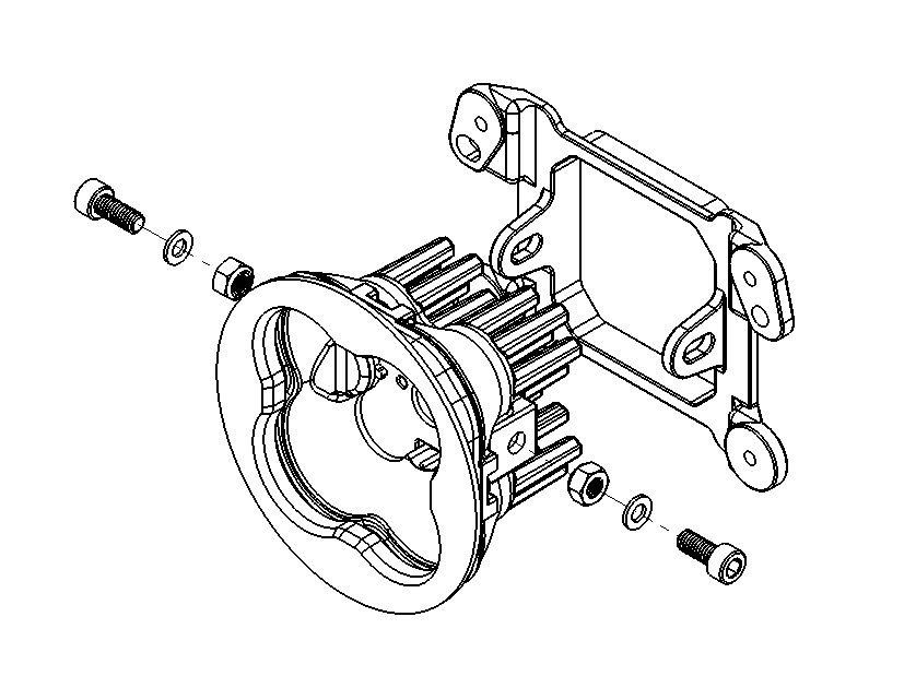
2. Add the Type MR steel adapters only when required. Fit a steel adapter to the side of each Type M bracket. The pair is mirrored: one steel adapter is on the right, the other on the left.
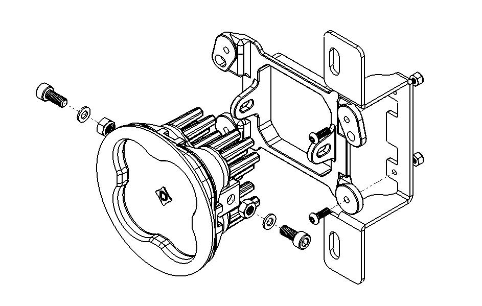
3. Access the factory fog lamp. Access varies with the vehicle and bumper. Unplug the factory connector, remove the lamp and retain the original mounting hardware. Align the new bracket with the factory mounting points, fit it securely and repeat on the other side.
Manufacturer installation demonstration; use the branch that matches your bumper.
Type MS: Sport plastic-bumper removal and installation
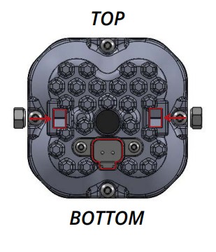
1. Assemble the Type MS bracket. Fit the nuts with nylon facing inward, then the supplied screws and washers. Observe the original TOP/BOTTOM orientation. Leave enough pivot movement for aiming.
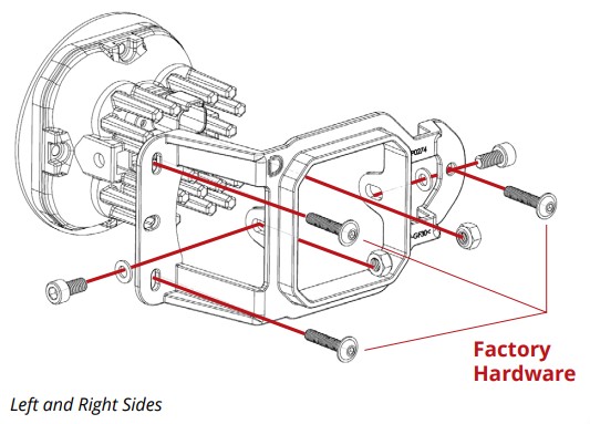
2. Remove the splash guard. Release the eight push rivets along its front, working both accessible sides of each rivet. Remove the two lower bolts with an 8mm socket, then remove the guard.
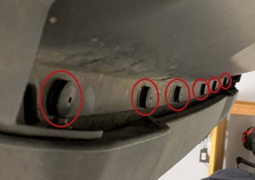
3. Remove the fog-light covers. Use a 7mm socket to remove the seven screws shown.
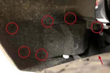
4. Remove the original lamp. Remove its three T20 screws with hand tools and keep them for the new bracket. Avoid power tools that can strip or heat the plastic.
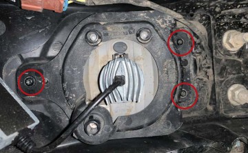
5. Fit the new lamp and bracket. Use the three original screws. The DT connector must be at the bottom and the SAE markings readable when installed. Repeat for the opposite side. Refit the covers and splash guard after operation and aim are checked.
Connect the main beam and optional backlight
Connect the lamp to the factory fog wiring with the included adapter. Test the main beam. If it does not illuminate, follow the supplied adapter instructions and try reversing the compatible connector 180 degrees. Do not force a connector or substitute an unmatched harness.
The amber backlight is a separate accent function, not the White or Yellow road-lighting beam. Connect its lead only to a suitable fused 12V circuit, following the supplied wiring instructions. Do not connect the backlight lead directly to the battery.
Backlit SS3 versions use the supplied four-pin connection and separate backlight lead. Main-beam operation remains on the factory fog controls. SmartSelect programming applies only to Dual Color DD8942, DD8943 and DD8944; fixed White and Yellow kits do not switch colour.
Set the cutoff before driving
1. Park on level ground 25 feet from a wall or garage door. The manufacturer’s photos below use another vehicle to demonstrate the same measurement and aiming method.
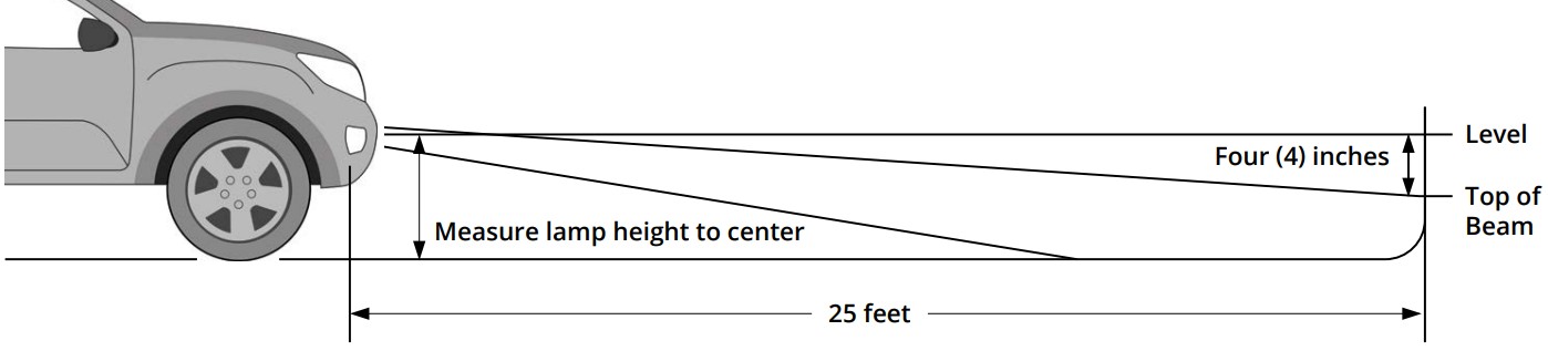
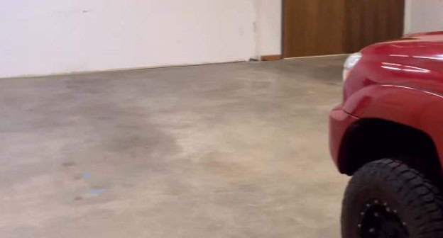
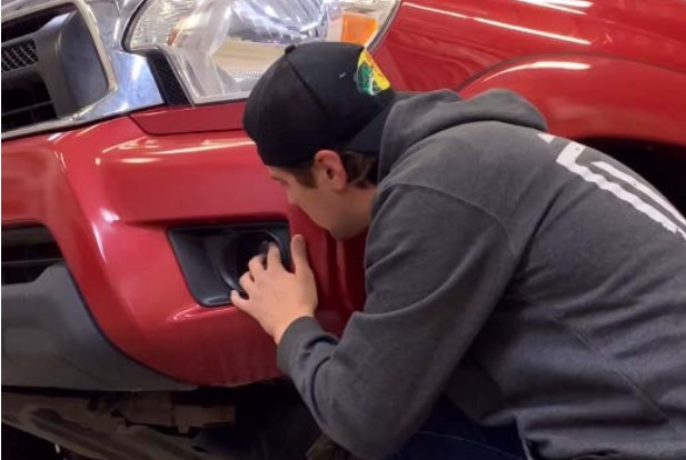
2. Loosen the 5/32-inch Allen pivot bolts just enough to adjust each pod.
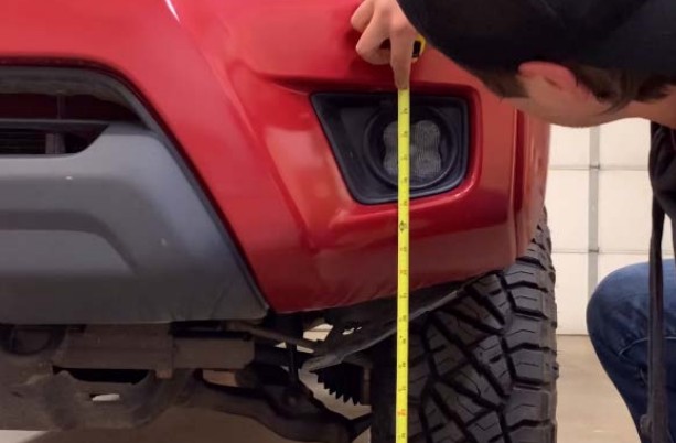
3. Measure from the ground to the centre of the lamp.
4. Mark that height on the wall, then a second line four inches lower.
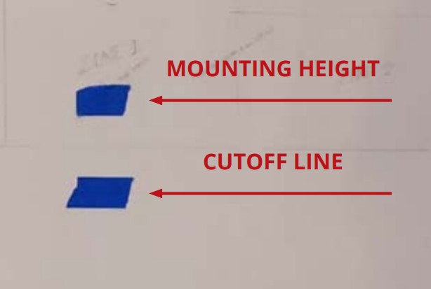
5. Set the top of the beam at the lower cutoff line. Retighten the pivot bolts without overtightening or power tools. Recheck both lamps and refit any removed covers.
Keep the original manufacturer instructions
Open the original Type MS mounting and aiming PDF · Open the Type MR mirrored-bracket PDF
The original documents include older product and warranty labels. For current coverage, use the exact product page and current manufacturer warranty terms.
JL fixed-colour SS3 kits · Dual Color Type M · Dual Color Type MR · Dual Color Type MS · Type M mounting parts